
User's Manual
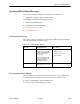
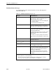
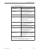
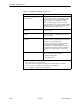
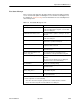


Table Of Contents
- Contents
- About This Guide
- About the FrameSaver DSL Unit
- User Interface and Basic Operation
- Configuration Procedures
- Configuration Options
- Overview
- Using the Easy Install Feature
- Setting Up So the Router Can Receive RIP
- Entering System Information and Setting the System Clock
- Configuration Option Tables
- Configuring the Overall System
- Configuring the Physical Interfaces
- Configuring Frame Relay for the Data Port
- Configuring ATM for the Network Interface
- Configuring Circuit and DLCI Records
- Configuring PVC Connections
- Setting Up Management and Communication Options
- Configuring Node IP Information
- Configuring Management PVCs
- Configuring General SNMP Management
- Configuring Telnet and/or FTP Session Support
- Configuring SNMP NMS Security
- Configuring SNMP Traps
- Configuring the Ethernet Port
- Configuring the Communication Port
- Configuring the COM Port to Support an External Modem
- Security and Logins
- Operation and Maintenance
- FTP Operation
- Troubleshooting
- Setting Up OpenLane for FrameSaver Devices
- Setting Up Network Health for FrameSaver Devices
- Menu Hierarchy
- SNMP MIBs and Traps, and RMON Alarm Defaults
- Connectors, Cables, and Pin Assignments
- Technical Specifications
- Equipment List
- Index

Operation and Maintenance
6-20
9783-A2-GB20-00
July 2000
Table 6-9. PVC Connection Status (2 of 2)
Field What It IndicatesStatus
EDLCI 0 to 62 For multiplexed DLCIs only.
Identifies an individual link/
connection embedded within a
DLCI.
Status
Identifies whether the physical
interfaces, LMIs, and DLCIs are all
enabled and active for this PVC
connection.
Active
1
H The PVC is currently active.
Inactive H The PVC is inactive because:
– Alarm conditions and network
and SLV communication
status indicate that data
cannot be successfully
passed.
– The unit has disabled the
interface or frame relay link
due to internal operating
conventions.
– Activation of an alternate
virtual circuit is not warranted;
that is, no alarm condition on
the primary destination link
has been detected.
Disabled H The PVC cannot be activated
and is essentially disabled as a
result of how the unit was
configured. Possible causes:
– The physical interface at one
or both ends of the PVC is/are
disabled.
– The frame relay link on one or
both ends of the PVC is/are
disabled.
Invalid H Some portion of the PVC
connection is not fully configured.
1
For the circuit to be active, both Source and Destination Statuses must be Active.