
User's Manual
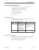
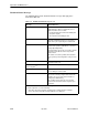
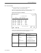


Table Of Contents
- Contents
- About This Guide
- About the FrameSaver DSL Unit
- User Interface and Basic Operation
- Configuration Procedures
- Configuration Options
- Overview
- Using the Easy Install Feature
- Setting Up So the Router Can Receive RIP
- Entering System Information and Setting the System Clock
- Configuration Option Tables
- Configuring the Overall System
- Configuring the Physical Interfaces
- Configuring Frame Relay for the Data Port
- Configuring ATM for the Network Interface
- Configuring Circuit and DLCI Records
- Configuring PVC Connections
- Setting Up Management and Communication Options
- Configuring Node IP Information
- Configuring Management PVCs
- Configuring General SNMP Management
- Configuring Telnet and/or FTP Session Support
- Configuring SNMP NMS Security
- Configuring SNMP Traps
- Configuring the Ethernet Port
- Configuring the Communication Port
- Configuring the COM Port to Support an External Modem
- Security and Logins
- Operation and Maintenance
- FTP Operation
- Troubleshooting
- Setting Up OpenLane for FrameSaver Devices
- Setting Up Network Health for FrameSaver Devices
- Menu Hierarchy
- SNMP MIBs and Traps, and RMON Alarm Defaults
- Connectors, Cables, and Pin Assignments
- Technical Specifications
- Equipment List
- Index

Operation and Maintenance
6-19
9783-A2-GB20-00
July 2000
PVC Connection Status
PVC connection statuses are selected from the Status menu.
Main Menu
→
Status
→
PVC Connection Status
Only PVC connections with Source DLCIs configured to be Active are shown.
This screen only appears when Service Type is set to Frame Relay.
PVC Connection Status Screen Example
main/status/connections 9783
Device Name: Node A 05/13/2000 06:03
Page 1 of 2
PVC CONNECTION STATUS
Source Primary Destination
Link DLCI EDLCI Link DLCI EDLCI Status
Port-1 201 Net1-FR1 300 0 Active
Port-1 202 Net1-FR1 1001 0 Active
Port-1 100 Net1-FR1 1001 2 Active
Port-1 204 Net1-FR1 1001 2 Active
Mgmt PVC Mgm205 Net1-FR1 (0,35) Active
Port-1 206 Net1-FR1 1001 Active
Port-1 207 Net1-FR1 1001 Active
Port-1 208 Net1-FR1 500 Active
Port-1 209 Net1-FR1 502 2 Inactive
Port-1 210 Net1-FR1 504 2 Inactive
––––––––––––––––––––––––––––––––––––––––––––––––––––––––––––––––––––––––––––––––
ESC for previous menu M
ainMenu Exit
R
efresh PgUp PgDn
If the No PVC Connections message appears instead of a list of PVC
connections, no PVC connections have been configured yet.
Table 6-9. PVC Connection Status (1 of 2)
Field
Status What It Indicates
Link
Identifies the cross-connection of
DLCIs configured for the unit.
Net1-FR1 H Source/destination is frame relay
link 1 on Network 1
Port-1 H User data port – Port-1
Mgmt PVC
Name
H Virtual circuit is a management
link that terminates in the unit,
where
Name
is the link name
DLCI
DLCI
(16–1007)
or
(
VPI,VCI
) (0–15,31–255)
Identifies an individual link.