
User's Manual
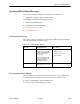
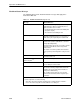
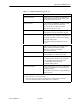
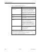
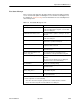
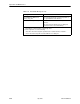
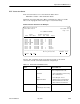


Table Of Contents
- Contents
- About This Guide
- About the FrameSaver DSL Unit
- User Interface and Basic Operation
- Configuration Procedures
- Configuration Options
- Overview
- Using the Easy Install Feature
- Setting Up So the Router Can Receive RIP
- Entering System Information and Setting the System Clock
- Configuration Option Tables
- Configuring the Overall System
- Configuring the Physical Interfaces
- Configuring Frame Relay for the Data Port
- Configuring ATM for the Network Interface
- Configuring Circuit and DLCI Records
- Configuring PVC Connections
- Setting Up Management and Communication Options
- Configuring Node IP Information
- Configuring Management PVCs
- Configuring General SNMP Management
- Configuring Telnet and/or FTP Session Support
- Configuring SNMP NMS Security
- Configuring SNMP Traps
- Configuring the Ethernet Port
- Configuring the Communication Port
- Configuring the COM Port to Support an External Modem
- Security and Logins
- Operation and Maintenance
- FTP Operation
- Troubleshooting
- Setting Up OpenLane for FrameSaver Devices
- Setting Up Network Health for FrameSaver Devices
- Menu Hierarchy
- SNMP MIBs and Traps, and RMON Alarm Defaults
- Connectors, Cables, and Pin Assignments
- Technical Specifications
- Equipment List
- Index

Operation and Maintenance
6-14
9783-A2-GB20-00
July 2000
Health and Status Messages
The following table provides Health and Status messages that apply to the
FrameSaver DSL unit.
Table 6-7. Health and Status Messages (1 of 3)
Message
What It Indicates
AIS at Network
1 An Alarm Indication Signal (AIS) is received by the
network interface. AIS is an unframed, all ones
signal. Possible reasons include:
H Upstream FrameSaver unit is transmitting AIS
(keep-alive signal).
H The network is transmitting an AIS.
Auto-Configuration Active Auto-Configuration feature is active, which allows
automatic configuration and cross-connection of
DLCIs as they are reported by the network LMI.
Back-to-Back Mode Active The operating mode has been configured for
back-to-back operation (
Main Menu
→
Control
→
Change Operating Mode)
.
The FrameSaver unit can be connected to another
FrameSaver unit without a frame relay switch
between them.
This feature is useful for product demonstrations
or for a point-to-point configuration using a leased
line.
CTS down to Port-1 Device The user data port CTS control lead on the
FrameSaver unit is off.
DLCI
nnnn
Down,
frame relay link
1,2
The DLCI for the specified frame relay link is down.
DTR Down from Port-1 Device The DTR control lead from the device connected to
the user data port is deasserted.
EER at Network
1 The error rate of the received network signal
exceeds the currently configured threshold. This
condition only occurs if the network interface is
configured for ESF framing.
This condition clears when the error rate falls
below the threshold value, which may take up to
15 minutes.
1
nnnn
indicates a DLCI number of 16 through 1007.
2
frame relay link
is one of the following:
– Net1-FR1. The frame relay link specified for the network interface, Network 1.
– Port-1. The frame relay link associated with the user data port.