
User's Manual
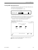
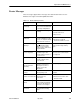
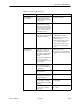
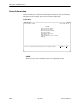
Table Of Contents
- Contents
- About This Guide
- About the FrameSaver DSL Unit
- User Interface and Basic Operation
- Configuration Procedures
- Configuration Options
- Overview
- Using the Easy Install Feature
- Setting Up So the Router Can Receive RIP
- Entering System Information and Setting the System Clock
- Configuration Option Tables
- Configuring the Overall System
- Configuring the Physical Interfaces
- Configuring Frame Relay for the Data Port
- Configuring ATM for the Network Interface
- Configuring Circuit and DLCI Records
- Configuring PVC Connections
- Setting Up Management and Communication Options
- Configuring Node IP Information
- Configuring Management PVCs
- Configuring General SNMP Management
- Configuring Telnet and/or FTP Session Support
- Configuring SNMP NMS Security
- Configuring SNMP Traps
- Configuring the Ethernet Port
- Configuring the Communication Port
- Configuring the COM Port to Support an External Modem
- Security and Logins
- Operation and Maintenance
- FTP Operation
- Troubleshooting
- Setting Up OpenLane for FrameSaver Devices
- Setting Up Network Health for FrameSaver Devices
- Menu Hierarchy
- SNMP MIBs and Traps, and RMON Alarm Defaults
- Connectors, Cables, and Pin Assignments
- Technical Specifications
- Equipment List
- Index
Operation and Maintenance
6-3
9783-A2-GB20-00
July 2000
Viewing LEDs and Control Leads
The FrameSaver DSL unit’s faceplate includes LEDs (light-emitting diodes) that
provide status on the unit and its interfaces.
The central site unit (supporting 64 PVCs) is shown.
00-16769
OK
OK
ALM
TEST
AT M
DSL
NetworkSystem
Port
FrameSaver
TM
SLV
FrameSaver
®
DSL
9783-C
The Display LEDs and Control Leads screen allows you to monitor a remote unit
and is useful when troubleshooting control lead problems. The appropriate
interfaces are shown on this screen, with the active status highlighted.
Main Menu
→
Status
→
Display LEDs and Control Leads
Display LEDs & Control Leads Screen
main/status/leds 9783-C
Device Name: Node A 05/13/2000 06:01
DISPLAY LEDS & CONTROL LEADS
DSL FR-ATM NAM
GENERAL
NETWORK1 PORT-1
OK Data Mode OK
Alarm LOS TXD
Test Training RXD
LCD DTR
ATM Mode RTS
–––––––––––––––––––––––––––––––––––––––––––––––––––––––––––––––––––––––––––––––
ESC for previous menu M
ainMenu Exit
R
efresh
Refresh the screen to view control lead transitions. LED and control lead
descriptions are in the sections that follow.