
Installation Manual

PARADOX.COM
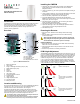
Jumper Settings
Single or Dual Edge Processing (J3)
This setting determines the Digital Signal Processing (DSP) operational
mode of the detector. Single Edge Processing mode should be used in
normal environments with minimal sources of interference. Dual Edge
Processing mode provides better false alarm rejection in the case where
the detector is placed near sources of interference that can adversely
affect the motion detector
Digital Shield™ Setting (J4)
In Normal Shield mode, the detector is set for normal environments. In
High Shield mode, the detector is set for high-risk environments (potential
interferences) and therefore provides greatly increased false alarm
immunity. However, response time and detector speed may be slower.
LED Setting (J5)
This setting enables or disables the LED. The LED will illuminate for four
seconds to indicate detected movement. The motion detector performs a
battery test every 12 hours. If the battery voltage is too low, the LED will
flash at 5-second intervals and the motion detector will send a low battery
signal to the receiver. A trouble will then be generated and transmitted to
the central monitoring station. The LED will flash rapidly when the motion
detector transmits a signal to the receiver.
After changing jumper settings, power cycle the PMD75N. Snap-on the
cover to close the anti-tamper switch or press and release the anti-tamper
switch to save the changes.
Testing the PMD75N
Open the cover to trigger the anti-tamper switch, then snap the cover back
into position. This will activate the motion detector’s walk-test mode for 3
minutes.
At 20°C (68°F), in Normal Shield (J4 = ON) mode and Single Edge
Processing mode (J3 = ON), you should not be able to cross more than
one complete zone (consisting of 2 beams, left and right sensor detecting
elements) in the coverage area with any kind of movement; slow/fast
walking or running.
In High Shield mode, the amount of movement required to generate an
alarm is doubled. The approximate width of a full-beam at 11m (35 ft) from
the detector is 1.8m (6 ft). When walk-testing, always move across the
detection path and not toward the detector.
NOTE: Walk-test mode is also activated for 3 minutes once the motion
detector is powered on.
Signal Strength Test
To verify the receiver's reception of the motion detector’s signal, perform a
signal strength test before finalizing the installation of the motion detector.
Before performing the test, make sure the batteries have been inserted
into the battery holder to power the detector. Also, verify that the motion
detector has been assigned to a zone. For more information on signal
strength tests and zone programming, refer to the appropriate receiver’s
Reference and Installation Manual. If the transmission is weak, relocating
the transmitter by a few inches can greatly improve the reception.
Alive Software
If the motion detector transmits 2 alarm signals (LED on for 4 sec.) within
five minutes, the detector falls into Energy Save mode where it won’t
transmit any alarm signals for approximately 3 minutes. Due to the motion
detector’s Alive Software, the red LED continues to flash to indicate a
detection even when in Energy Saver mode. Once the 3-minute Energy
Save mode ends, the motion detector returns to normal operation.
NOTE: If the detector’s cover is removed and then replaced while in
Energy Save mode, the first detection will trigger an alarm signal.
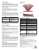
Beam Pattern
Top View
Side View
Technical Specifications
FCC and Industry Canada Compliance Statement
This device complies with FCC Rules Part 15 and with Industry Canada license exempt RSS standard(s). Operation is
subject to two conditions:
1.This device may not cause harmful interference
2.This device must accept any interference that may be received or that may cause undesired operation.
Le present appareil est conforme aux CNR d'Industrie Canada applicables aux appareils radio exempts de licence.
L'exploitation est autorisee aux deux conditions suivantes :
1. l'appareil ne doit pas produire de brouillage, et
2. l'utilisateur de l'appareil doit accepter tout brouillage radioelectrique subi, meme si le brouillage est susceptible d'en
compromettre le fonctionnement.
*FCC ID: KDYPMD75N
IC: 2438A-PMD75N
†
Battery life expectancy will vary according to the check-in time interval and the amount of traffic (movement) the
detector has processed. A higher check-in time interval and higher traffic will lower battery life.
FCC WARNING
This equipment has been tested and found to comply with the limits for a Class B digital device, pursuant to Part 15 of
the FCC Rules. These limits are designed to provide reasonable protection against harmful interference in a residential
installation. This equipment generates, uses and can radiate radio frequency energy and, if not installed and used in
accordance with the instructions, may cause harmful interference to radio communications.
However, there is no guarantee that interference will not occur in a particular installation. If this equipment does cause
harmful interference to radio or television
reception, which can be determined by turning the equipment off and on, the user is encouraged to try to correct the
interference by one or more of the following measures:
• Reorient or relocate the receiving antenna.
• Increase the separation between the equipment and the receiver.
• Connect the equipment into an outlet different from that to which the receiver is connected.
• Consult the dealer or an experienced radio/TV technician for help.
Changes or modifications to this equipment not expressly approved by the party responsible for compliance (Paradox
Security Systems Ltd.) could void the user’s authority to operate the equipment.
Feature LED Status Indicator
J3
Processing Type
OFF = Dual edge
ON = Single edge
J4
Digital Shield sensitivity
OFF = High Shield (low sensitivity)
ON = Normal Shield (high
sensitivity)
J5
Alarm LED (Red)
OFF = Disabled
ON = Enabled
Specification Description
Sensor Type Two dual opposed infrared sensors
Coverage - 90° (standard) 11m x 11m (35 ft x 35 ft)
Pet Immunity Up to 40 kg (90 lbs)
Detector Speed 0.2m to 3.5m/sec. (0.6 ft to 11.5 ft/sec.)
Installation Height 2.1m to 2.7m (7 ft to 9 ft)
RF Frequency
433* or 868 MHz
Lens 2nd generation Fresnel lens, LODIFF®,
segments
Power 4.5 Vdc (3 x 1.5 Vdc “AAA” alkaline batteries)
Low Battery 3.2V
Battery Life
†
Lowest check-in setting: 3 years
Highest check-in setting: 1.5 years
Transmitter Range 35m (115 ft) with MG6250
70m (230 ft) with MG5000 / MG5050 / RTX3
Anti-Tamper Switch Yes
Operating Temperature 0°C to +50°C (+32°F to +122°F)
Certifications EN 50131-2-2, Security Grade 2,
EN 50130-5 Environmental Class II
EN 50131-6 Type C
Certification Body: Applica Test and
Certification
Compatibility MG5000, MG5050, MG5075, MG6250,
RTX3, and RX1
3m
(10ft)
1.5m
(5ft)
01.5m
(5ft)
3m
(10ft)
90°
0
2.1m
(7ft)
1.5m
(5ft)
3m
(10ft)
6m
(20ft)
9m
(30ft)
11m
(35ft)
Warranty
For complete warranty information on this product, please refer to the Limited Warranty Statement
found on the website: www.paradox.com/terms or contact your local distributor. Specifications may
change without prior notice.
Patents
US, Canadian and international patents may apply. Paradox is a trademark or registered trademark of
Paradox Security Systems (Bahamas) Ltd.