
User's Manual
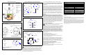

Figure 1: Detector Overview
Figure 2: Mounting
Figure 3: Single Residence with One Sleeping Area
Figure 4: Single Residence with Two Sleeping Areas
Figure 5: Locations for Multi-floor Residence
Figure 6: Alternative Mounting Locations
The following caution is required by the California State Fire Marshall:
“Early warning fire detection is best achieved by the installation of fire detection
equipment in all rooms and areas of the household as follows: (1) A smoke
detector installed in each sleeping area (in the vicinity, but outside of the
bedrooms) and (2) Heat or smoke detectors in the living rooms, dining rooms,
bedrooms, kitchens, hallways, attics, furnace rooms, closets, utility and storage
rooms, basements and attached garages.”
For your information, NFPA Standard 74, Section 2-4 reads as follows:
“2-4.1.1 Smoke detectors shall be installed outside of each separate sleeping
area in the immediate vicinity of the bedrooms and on each additional story of
the family living unit including basements and excluding crawl spaces and
unfinished attics.
The provisions of 2-4.1.1 represent the minimum number of detectors required
by this standard, It is recommended that the householder consider the use of
additional smoke detectors for increased protection for those areas separated by
a door from the areas protected by the required smoke detectors under 2-4.1.1
above. The recommended additional areas are living room, dining room,
bedroom(s), kitchen, attic (finished or unfinished), furnace rooms, utility room,
basement, integral or attached garage and hallways not included in 2-4.1.1
above. However, the use of additional remains the option of the householder.”
We recommend complete coverage and use of additional smoke detectors.
Locations to Install the Smoke Detector in Mobile Homes
and RVs
Mobile homes and RVs built after 1978 were designed and insulated to be
energy-efficient. In mobile homes and RVs built after 1978, smoke detectors
should be installed as outlined above. Older mobile homes and RVs may have
little or no insulation compared to current standards. Outside walls and roofs are
often made of non-insulated metal which can transfer thermal energy flow from
outdoors. This makes the air right next to them hotter or colder than the rest of
the inside air. These layers of hotter or colder air can keep smoke from reaching
the smoke detector. Therefore, install smoke detectors in such units only inside
walls. Place them between XCM (4”X) and XCM (6”) from the ceiling. If you are
not sure how much insulation is in your mobile home or RV, then install the
detector in each room for security. Before you install any detector, please read
the section “Detection Parameters” on page 1.
FCC Compliance Statement
Changes or modifications not expressly approved by Paradox Security
Systems could void your authority to use this equipment.
This equipment generates and uses radio frequency energy and if not installed
and used properly, in strict accordance with the manufacturer’s instructions, may
cause interference to radio or television reception. It has been type tested and
found to comply with the limits of Class B device in accordance with the
specifications in Subpart “B” if Part 15 of FCC Rules, which are designed to
provide reasonable protection against such interference in any residential
installation. However, there is no guarantee that interference will not occur in a
particular installation. If this equipment does cause interference to television or
radio reception, which can be determined by turning the equipment off and on,
the user is encouraged to try to correct the interference by one or more of the
following measures:
• Re-orient the receiving antenna.
• Relocate the alarm control with respect to the receiver.
• Move the alarm control away from the receiver.
• Connect the alarm control into a different outlet so that alarm control and
receiver are on different circuits.
If necessary, the user should consult the dealer or an experienced radio/
television technician for additional suggestions. The user may find the following
booklet prepared by the FCC helpful: “How to Identify and Resolve Radio/
Television Interference Problems”. This booklet is available from the U.S.
Government Printing Office, Washington, D.C. 20402, Stock # 004-000-00345-4.
Industry Canada Compliance Statement
This Class “B” digital apparatus meets all requirements of the Canadian
interference-causing equipment regulations.
IC: 2438A-0MnS7K1
“The term “IC:” before the radio certification number only signifies that Industry
Canada technical specifications were met.”
*The following batteries are acceptable for proper smoke detector operation:
Eveready #522, #1222, #216, Duracell #MN1604 and Gold Peak #1604P,
#1604S.
Specifications may change without prior notice.
For the latest information on product approvals, such as UL and CE, please visit our Web site at www.paradox.ca. One or more of
the following US patents may apply: 6215399, 611256, 5077549, 5751803, 5721542, 5287111, 5119069, and 5077549. LODIFF®
lens: patent #4,787,722 (U.S.). Canadian and International patents may also apply: LODIFF® a registered trademark of Fresnel
Technologies Inc. Digigard and Shield are trademarks of Paradox Security Systems.
Warranty
The Seller warrants its products to be free from defects in materials and workmanship under normal use for a period of one year.
Except as specifically stated herein, all express or implied warranties whatsoever, statutory or otherwise, including without
limitation, any implied warranty of merchantability and fitness for a particular purpose, are expressly excluded. Because Seller
does not install or connect the products and because the products may be used in conjunction with products not manufactured by
the Seller. Seller cannot guarantee the performance of the security system. Seller obligation and liability under this warranty is
expressly limited to repairing or replacing, at Seller’s option, any products not meeting the specifications. In no event shall the
Seller be liable to the buyer or any other person for any losses or damages whether direct or indirect or consequential or
incidental, including without limitation, any damages for lost profits stolen goods, or claims by any other party, caused by defective
goods or otherwise arising from the improper, incorrect or otherwise faulty installation or use of the merchandise sold.
© 2003 Paradox Security Systems Ltd.
A = Test button
B = Cover slots
C = Transmitter PCB
D = Antenna
E = Sensing chamber
F = Horn
G = LED
H = Battery connector
L = Lock tab
M = Battery
A
B
C
D
E
F
B
B
G
H
L
M
Turn counter-clockwise to lock to mounting
bracket.
Gently pull, then turn clockwise to unlock
from mounting bracket.
B
A
C
D
D
1) Remove tamperproof thread from lock slot (A), then align with
preferred lock tab (B).
2) Insert screws (C) into preferred keyhole slots (D).
Mounting bracket
B
Dining Room Kitchen
Living Room
Bedroom
Bedroom
Bedroom
= Detectors for minimum security.
= Detectors for additional
security.
Sleeping
area
Bedroom
Bedroom
Bedroom
Bedroom
Family Room
Living Room
= Detectors for minimum security.
= Detectors for additional
security.
Kitchen
Bedroom
Bedroom
Living Room
Kitchen
Bedroom
Bedroom
Family Room
Sleeping
areas
= Detectors for minimum
security.
Bedroom
Bedroom
Study
Room
Bedroom
Basement
Kitchen
Center of ceiling
best location
Acceptable
location
Never
install in
this area
10cm
(4”)
10cm
(4”)
15cm
(6”)
15cm
(6”)
Horizontal distance
from peak
1m
(3.2ft)
Sloped ceiling
Corner
mounting
TECHNICAL SPECIFICATIONS
Detector Type
Power
9Vdc Alkaline battery
*
Sensitivity 2.3±1.2%ft
Alarm Sound Output 85dB at (Xcm) (10ft)
Indicator Light Red LED flashed once every 45 sec.
Low Battery Life Up to 30 days
Relative Humidity 10% to 85%
Dimensions 140mm (5.5”) X 45mm (1.47”)
Supervisory Transmission Frequency
UL, ULC
64 minute intervals
Supervisory Transmission Frequency
ULC
12 minute intervals
Sounder Alarm Pattern UL, EU Evacuation temporal pattern
Sounder Alarm Pattern ULC Continuos beeps