Wireless Receiver Module V1.
INTRODUCTION ........................................................................................3 Technical Specifications ...................................................................................3 System Features ...............................................................................................3 INSTALLATION .........................................................................................4 Location ........................................................
The Omnia Wireless Receiver Module (OMN-RCV3) allows you to add up to 8 fully supervised Omnia wireless motion detectors and/or door contacts, and up to 8 programmable remote controls to the Spectra system. 1.
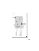
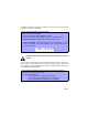
The following sections will detail how to mount and connect the Omnia Wireless Receiver Module (OMN-RCV3). 2.1 LOCATION Mount the Omnia Wireless Receiver on a wall allowing at least 5cm (2”) around the module to permit adequate ventilation and heat dissipation. Select a site that is not susceptible to drastic temperature changes. Avoid installation near or in the path of strong RF fields (i.e.
Figure 2.
To successfully install an Omnia wireless system to your Spectra system, ensure that the following steps are completed: 1. Install the Omnia Receiver. Connect the Omnia Receiver to the Spectra control panel and power up. 2. Assign the remote controls if necessary. 3. Assign the transmitters (door contacts and motion detectors), and program their zones. 4. Install the transmitters. Insert the batteries, and close the transmitter cover. 5. Wait for the control panel to be in “ready” mode.
3.2.1 ASSIGNING DETECTORS AND DOOR CONTACTS TO THE RECEIVER SECTIONS [601] TO [608] In Spectra systems, up to 8 wireless transmitters (detectors and door contacts) can be assigned to each Receiver Module. Section [601] to [608] represent expansion inputs 1 to 8 respectively. For example, section [601] is assigned to expansion input 1, section [602] is assigned to expansion input 2, etc. (refer to Table 3.1).
The serial number is located on the inside of the transmitter or you can use the Unknown Serial Number Display method (refer to section 3.4 on page 10) to determine its serial number. The transmitters must be activated once having been assigned to the Receiver. To activate a transmitter, insert the batteries and close the cover. To ensure proper synchronization between the receiver and the transmitter, open and close the zone corresponding to the transmitter. 3.2.
acceptable. Sometimes moving the transmitter or receiver by a small amount will greatly increase the signal reception. How to view a transmitter’s signal strength. In step 3 in section 3.1 on page 6: 1. Enter the desired [SECTION NUMBER] (631 to 638). 2. Press the transmitter’s tamper switch, or open the corresponding zone. On an LED keypad: The keypad will illuminate numbers 1 to 8. On an LCD keypad: The keypad will display from 1 to 8 characters on the screen.
3.4 VIEWING UNKNOWN SERIAL NUMBERS SECTION [630] This feature will display the serial number of any Omnia motion detector or door contact on any Spectra keypad. How to view unknown transmitter serial numbers. In step 3 in section 3.1 on page 6: 1. Enter section [630]. 2. Press the tamper switch of any Omnia wireless motion detector or door contact. When the signal has been received, the keypad will emit a confirmation beep (“Beep-Beep-Beep-Beep-Beep”). 3.
a report code to the monitoring station. For details refer to the appropriate Spectra Reference & Installation Manual. How to enable check-in supervision. In step 3 in section 3.1 on page 6: 1. Enter section [610]. 2. Enable or disable option [1]. Option [1] OFF = Check-In Supervision disabled (default) Option [1] ON = Check-In Supervision enabled 4.
4.3 LOW BATTERY SUPERVISION When the battery voltage of an Omnia wireless transmitter (motion detector or door contact) drops to less than 3.1V, the Spectra control panel will send a low battery report code to the monitoring station, and a trouble will appear in the keypad’s trouble display. 4.4 ON-BOARD MODULE TAMPER SUPERVISION ZONE ASSIGNMENT SECTION [615]: The OMN-RCV3 comes equipped with an on-board tamper switch.
The Omnia Wireless Receiver Module accepts up to eight fully programmable remote controls. Programming the remote controls is accomplished in three steps: 1. The remote controls must be assigned to the Wireless Receiver Module. 2. The remote controls from the Wireless Receiver Module must be assigned to User Access Codes. 3. The buttons on the remote controls must be programmed.
For installations using a Spectra control panel version 2.0 or higher: How to assign a remote control to the receiver module (V2.0 and higher). In step 3 in section 3.1 on page 6: 1. Enter desired [SECTION NUMBER] (731 to 738). 2. Press any button on the remote control twice, or until the confirmation beep sounds (“Beep-Beep-Beep-Beep-Beep”). If you are having trouble assigning the remote control, the environment may be too noisy.
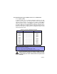
Sections [711] to [718] represent the remote controls assigned to sections [721]/ [731] to [728]/[738] (refer to section 5.1 on page 13). For example, the buttons for the remote control assigned in section [731] will be programmed in section [711]. How to program the remote control buttons: In step 3 in section 3.1 on page 6: 1. Enter the desired [SECTION NUMBER] (711 to 718). 2. Enter the hexadecimal value (0 to D) of the desired options from Table 5.2 on page 16 in the appropriate space (refer to Table 5.
Table 5.
Figure 5.4: Remote Control Button Identification The User Code assigned to the remote control (refer to section 5.2 on page 14) must have the same User Options enabled. For example, if you enable the Force Arming button option, you must enable the appropriate Force Arming user option. Also, if you enable any Panic button options, you must enable the Panic options in the Spectra control panel (refer to the appropriate Spectra Reference & Installation Manual). 5.
For installations using a Spectra control panel version 2.0 or higher: How to delete a remote control (Spectra version 2.0 or higher): In step 3 in section 3.1 on page 6: 1. Enter the desired [SECTION NUMBER] (731 to 738). 2. Press the [FORCE] button. 5.5 REPLACING THE REMOTE CONTROL BATTERIES How to replace the remote control batteries. 1. Remove the two screws from the back of the remote control and remove the back cover. 2. Remove the old batteries from inside the remote control. 3.
Section [601] to [608] Description - Assigning detectors and door contacts to the receiver - Deleting the detectors and door contacts [610] Option [1]: Check-in supervision Option [2]: Check-in supervision base time Option [5]: Check-in supervision time value [615] On-board module tamper supervision zone assignment [630] Viewing unknown serial numbers [631] to [638] Viewing the detector and door contact signal strengths [701] to [708] Assigning the remote controls to user access
WARRANTY The Seller warrants its products to be free from defects in materials and workmanship under normal use for a period of one year. Except as specifically stated herein, all express or implied warranties whatsoever, statutory or otherwise, including without limitation, any implied warranty of merchantability and fitness for a particular purpose, are expressly excluded.