
User's Manual
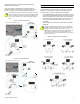
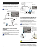

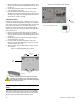
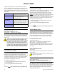


Table Of Contents
- Introduction
- About Magellan and this Manual
- Conventions
- Specifications
- Quick Setup
- Installation
- AC Power
- DC Power
- Backup Battery Pack
- Auxiliary Output
- Telephone Line Connections
- Programmable Outputs (PGMs)
- Hardwire Zone Connections
- WinLoad Connection
- UIP-256 Universal In-Field Programmer Connection
- X10 Transmitter Connection (MG-6160 only)
- Connecting a Paradox Memory Key (PMC-3)
- Location and Mounting
- Connecting the Radio Antenna (MG-6160 only)
- Programming Methods
- WinLoad Installer Upload/Download Software
- Programming Using the Built-in Keypad
- Programming Using a Paradox Memory Key
- User Codes
- User Code Length
- Installer Code
- Maintenance Code
- System Master Code
- Duress Code
- Zone Programming
- Zone Programming Overview
- Zone Definitions
- Zone Options
- Zones 31 and 32 Become Hardwire Zones
- EOL (End-Of-Line) Zones
- Assigning Wireless Zone Transmitters
- Assigning Wireless Doorbells to the Console
- Deleting Assigned Wireless Transmitters
- Viewing Wireless Transmitter Signal Strength
- Assigning Remote Controls
- Programming the Remote Control’s Buttons
- Assigning Wireless Keypads
- Assigning Wireless Repeaters
- Wireless Repeater Options
- Arming and Disarming
- Regular Arming Switches to Stay Arming
- Regular Arming Switches to Force Arming
- Stay Arming Switches to Force Arming
- Timed Auto-Arming
- No Movement Auto-Arming
- Auto-Arming Options
- One-Touch Arming
- Exit Delay
- Bell Squawk on Arm/Disarm with Remote Control
- No Exit Delay when Arming with Remote Control
- Exit Delay Termination
- Follow Zone Switches to Entry Delay 2
- Closing Delinquency Timer
- Stay Arm Siren Delay
- Alarm Options
- Bell Cut-off Timer
- Wireless Transmitter Supervision Options
- Check-in Supervision Options
- Tamper Recognition Options
- Wireless PGM Supervision Options
- Wireless Keypad Supervision Options
- Wireless Repeater Supervision Options
- Wireless PGM Console Supervision Options (Follow Alarm/Follow Bell)
- Backup Alarm Reporting Option
- Panic Alarms
- Reporting and Dialer Settings
- Report Codes
- Console Telephone Numbers
- Console Account Number
- Reporting Formats
- Event Call Direction
- Delay Between Dialing Attempts
- Alternate Dial Option
- Force Dial Option
- Dialing Method
- Pulse Ratio
- Switch to Pulse Dialing on 5th Attempt
- Telephone Line Monitoring (TLM)
- Recent Close Delay
- Auto-Test Report
- Power Failure Report Delay
- Disarm Reporting Options
- Zone Restore Report Options
- RF Jamming Supervision
- Programmable Outputs
- Assigning PGMs
- Setting PGM Function
- Onboard PGM Activation Event
- Onboard PGM Deactivation Event
- Onboard PGM Delay
- PGM Normal State (Onboard Only)
- PGM X10 Option (MG-6160 Only / Onboard Only)
- Wireless PGM Activation Event
- Wireless PGM Deactivation Event
- Wireless PGM Delay
- System Settings
- Software Reset
- Installer Lock
- Console Tamper Supervision
- Console Audible Trouble Warning
- FM Tuner Option (MG-6160 only)
- Daylight Savings Time
- AC Power Failure Warning
- The Trouble Display
- WinLoad Software Settings
- Panel Answer Options
- Panel Identifier
- PC Password
- PC Telephone Number
- Call Back Feature
- Appendix 1: Automatic Report Code List
- Appendix 2: Ademco Contact ID Report Code List
- Index

Paradox Magellan Systems 11
apply power to the console. For more information, see
Programming Using a Paradox Memory Key on page 13.
Figure 13: Connecting a Paradox Memory Key (PMC-3)
The installer should verify the proper installation of the memory
key.
Location and Mounting
Location
The locations of Magellan and its wireless transmitters affect the
overall performance of the wireless system. To ensure the best
signal reception, the following list of location criteria should be
respected whenever possible:
• Select an installation site that is free of obstacles that reflect
and absorb radio frequency (RF) signals, as well as
interference that may distort signals. Avoid installation near
or in the path of strong RF fields (i.e., neon lights,
computers), and on or near metal objects, circuit breaker
boxes, air conditioners and heater ducts since they may
cause interference and reduce the console’s sensitivity.
• Select a site that is not susceptible to drastic temperature
changes.
• Mount the Magellan console as central as possible to the
proposed placement of the wireless transmitters.
• Mount the Magellan console as high as possible.
• Avoid installing Magellan in the basement as the range of
the console is reduced when installed below ground level.
However, if it is absolutely necessary to install the console in
the basement, install the console as high as possible.
• Install the Magellan console on a wall allowing at least 5cm
(2”) around the console to permit adequate ventilation and
heat dissipation.
The Wall Plate
Magellan uses a plastic wall plate to stay mounted on a wall. The
wall plate is also used for tabletop mounting to cover the back of
the console as well as keep any wires within their respective wire
slots. After choosing an appropriate location (see Location on
page 11), mount the wall plate onto the Magellan console with
two screws as described in Mounting Magellan on the Wall on
page 11 or Tabletop Mounting on page 12.
Figure 14: Wall Plate
Figure 15: Mounting Magellan onto the Wall Plate
Figure 16: Magellan’s Back Plate
Mounting Magellan on the Wall
Magellan can be mounted on a wall by first securing the wall
plate (see The Wall Plate on page 11) to the wall and then
mounting the Magellan console on the secured wall plate as
shown in Figure 15 on page 11 and Figure 16 on page 11. To do
so:
1. Place the wall plate on the desired spot of the wall.
2. Drill and insert screws into holes labeled A as shown in
Figure 14 on page 11.
3. Place the console back plate flush against the mounted wall
plate.
Jumper ON:
Read from and/or write to memory key
Jumper OFF:
Write protected (read from memory key only)
A (x7)
B
C
B
C
D
D
E