
Installation Guide
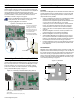
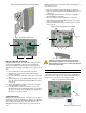
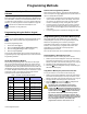
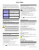
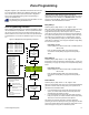


Table Of Contents
- Introduction
- About Magellan and this Manual
- Conventions
- Specifications
- Quick Setup
- Installation
- AC Power
- Backup Battery Pack
- Telephone Line Connections
- Programmable Outputs (PGMs)
- Hardwire Zone Connections
- WinLoad Connection
- UIP-256 Universal In-Field Programmer Connection
- X10 Transmitter Connection
- Connecting a Paradox Memory Key (PMC-3)
- Location and Mounting
- Connecting the Radio Antenna
- Programming Methods
- WinLoad Installer Upload/Download Software
- Programming Using the Built-in Keypad
- Programming Using a Paradox Memory Key
- User Codes
- User Code Length
- Installer Code
- Maintenance Code
- System Master Code
- Duress Code
- Zone Programming
- Zone Programming Overview
- Zone Definitions
- Zone Options
- Zones 15 and 16 become Hardwire Zones
- EOL (End-Of-Line) Zones
- Wireless Programming
- Assigning Wireless Zone Transmitters
- Assigning Wireless Doorbells to the Console
- Deleting Assigned Wireless Transmitters
- Viewing Wireless Transmitter Signal Strength
- Assigning Remote Controls
- Programming the Remote Control’s Buttons
- Arming and Disarming
- Regular Arming Switches to Stay Arming
- Regular Arming Switches to Force Arming
- Stay Arming Switches to Force Arming
- Timed Auto-Arming
- No Movement Auto-Arming
- Auto-Arming Options
- One-Touch Arming
- Exit Delay
- Bell Squawk on Arm/Disarm with Remote Control
- No Exit Delay when Arming with Remote Control
- Exit Delay Termination
- Follow Zone Switches to Entry Delay 2
- Closing Delinquency Timer
- Alarm Options
- Bell Cut-off Timer
- Wireless Transmitter Supervision Options
- Tamper Recognition Options
- Check-in Supervision Options
- Panic Alarms
- Reporting and Dialer Settings
- Report Codes
- Console Telephone Numbers
- Console Account Number
- Reporting Formats
- Event Call Direction
- Delay Between Dialing Attempts
- Alternate Dial Option
- Force Dial Option
- Dialing Method
- Pulse Ratio
- Switch to Pulse Dialing on 5th Attempt
- Telephone Line Monitoring (TLM)
- Recent Close Delay
- Auto-Test Report
- Power Failure Report Delay
- Disarm Reporting Options
- Zone Restore Report Options
- Programmable Outputs
- PGM Activation Event
- PGM Deactivation Event
- PGM Delay
- PGM Normal State
- PGM X10 Option
- System Settings
- Software Reset
- Installer Lock
- Console Tamper Supervision
- Console Audible Trouble Warning
- FM Tuner Option
- Daylight Savings Time
- AC Power Failure Warning
- The Trouble Display
- WinLoad Software Settings
- Panel Answer Options
- Panel Identifier
- PC Password
- PC Telephone Number
- Call Back Feature
- Appendix 1: Ademco Contact ID Report Code List
- Index

16 Reference & Installation Manual
Intellizone Delay Timer
Section [065]: 010 to 255 seconds; Default = 48 seconds
Enter the desired 3-digit value into section [065] to program
the Intellizone Delay Timer.
Delay Before Alarm Report Code Transmission
Sections [001] to [016]: Zones 1 to 16; option [7]
Option [7] OFF =Delay alarm transmission disabled (default)
Option [7] ON =Delay alarm transmission enabled
This feature is commonly used with Entry Delay zones to reduce
false alarms created by new users who may not disarm the
system in time. This feature works as follows:
• When an alarm condition occurs on a zone with this option
enabled, the console enables the bell/siren output, but does
not report the alarm to the central station until the end of the
Alarm Before Transmission Delay.
• During this period, disarming the system disables the bell/
siren output and cancels the report code transmission.
Alarm Transmission Delay
Section [075]: 001 to 255 seconds; 000 = Disabled; Default = 0
seconds
Enter the desired 3-digit delay value into section [075] to
program the Alarm Transmission Delay.
Remote Panic Disarm Lock Delay
Section [078]: 001 to 255 seconds; 000 = Disabled; Default = 20
seconds
When a panic alarm is generated through the use of a remote
control, the system cannot be disarmed by remote control during
the Remote Panic Disarm Lock Delay.
Enter the desired 3-digit delay value into section [078] to
program the Remote Panic Disarm Lock Delay.
Force Zones
Sections [001] to [016]: Zones 1 to 16; Option [8]
Option [8] OFF =Force zone disabled
Option [8] ON =Selected zone is Force enabled (default)
Any open Force zones at the time of arming will be considered
deactivated by the console. If during this period a deactivated
zone is closed, the console will revert that zone to active status.
Consequently, the console will generate an alarm if the zone is
breached.
Fire zones cannot be programmed with the Force Zone
option because the console will not bypass a Fire zone when
the system is being Force armed.
Stay Delay Zones
Section [094]: Options [1]
Option [1] OFF =Stay Delay zone disabled (default)
Option [1] ON =Stay Delay zone enabled
When a Stay Delay zone is armed using the Stay or Instant
arming methods and the zone is triggered, an alarm will not
generate until the programmed Stay Delay elapses. A zone
defined as Stay Delay 1 follows the Entry Delay 1 Timer of its
assigned partition. Likewise, a zone defined as Stay Delay 2
follows the Entry Delay 2 Timer of its assigned partition. To
program the Entry Delay Timers, refer to Entry Delay 1 and Entry
Delay 2 on page 13.
Zones 15 and 16 become Hardwire Zones
Section [095]: Options [1] and [2]
Option [1] OFF = Wireless zone 15 remains unchanged (default)
Option [1] ON = Wireless zone 15 uses the on-board hardwire
zone input 1
Option [2] OFF = Wireless zone 16 remains unchanged (default)
Option [2] ON = Wireless zone 16 uses the on-board hardwire
zone input 2
The Magellan console comes with two on-board zone inputs,
hardwire zone inputs 1 and 2. Section [095] options [1] and [2]
allow you to convert zones 15 and 16 from wireless to hardwire
by allowing you to connect hardwire detection devices (i.e. door
contact) to zone inputs 1 and 2.
• With section [095] option [1] ON, zone 15 is connected to
zone input 1.
• With section [095] option [2] ON, zone 16 is connected to
zone input 2.
EOL (End-Of-Line) Zones
Section [095]: Option [3]
Option [3] OFF = Hardwire zones 1 & 2 do not require EOL
resistors (default)
Option [3] ON = Hardwire zones 1 & 2 require EOL resistors
This feature only applies to Magellan’s on-board zone
inputs. Section [095] options [1] and/or [2] (see Zones 15
and 16 become Hardwire Zones on page 16) must be ON in
order to use this feature.
If the hardwire detection devices connected to Magellan’s zone
inputs 1 and 2 have input terminals that require 1K9 end of line
resistors, enable (ON) section [095] option [3]. For details on
using EOL resistors, refer to page 8.