
Installation Instructions


Magellan 5
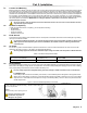
2.7 Metal Box Installation
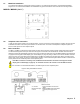
The crosses and dotted line represent the mounting location. If you need specific dimensions, contact Paradox Distributor
Support. For UL recommended installation for the MG5000 only, place the PCB one notch lower than the mounting location.
MG5050 / MG5050 (11x11”)
2.8 Telephone Line Connection
In order to report system events to the monitoring station, you must connect the incoming telephone company wires into the TIP
and RING connections of the control panel and then run the wires from T1 and R1 to the telephone or telephone system as
shown in PCB Layouts for each respective panel.
2.9 Bell Connection
The BELL+ and BELL- terminals power bells, sirens and other warning devices requiring a steady voltage output during an alarm.
The bell terminal supplies 12Vdc upon alarm and can support one 30-watt or two 20-watt sirens. The bell connection uses a
fuseless circuit and will automatically shut down if the current exceeds 3A. When this occurs the Maximum Bell Current failure will
only appear in the keypad’s trouble display (see Trouble Display on page 53) during an alarm. If the load on the BELL terminals
returns to normal, the control panel will re-instate power to the BELL terminals during the next alarm. When connecting sirens,
please verify correct polarity. Connect the positive lead to the BELL+ terminal and the negative lead to the BELL- terminal of the
control panel as shown in PCB Layouts for each respective panel.
If the BELL connection is not being used, the Bell Disconnected failure will remain in the keypad’s trouble
display (see Trouble Display on page 53). To avoid this connect a 1K resistor across the BELL terminals.
For connection of a self-contained bell/siren, see PCB Layouts for each respective panel.
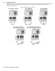
Figure 2: Relay and PGM Connections