
Data Sheet

PE IoT Engine
Datasheet
Document No. [DOC-DAT-0023-04] Date of last revision [04.03.2021]
Page 16 / 30
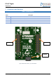
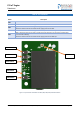
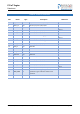
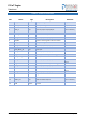
Table 10 – Pinout of J1 Connector
PIN
Name
Type
Description
Reference
1
V_BAT
Power
Optional external backup battery
V
BAT
2
GPIO_14
I/O
General purpose input/output
V
DIGITAL
3
I2C SDL
I/O
I2C data
V
DIGITAL
4
GPIO_9
I/O
General purpose input/output
V
DIGITAL
5
GPIO_11
I/O
General purpose input/output
V
DIGITAL
6
RXD
O
Serial Interface for debugging
V
DIGITAL
7
GPIO_12
I/O
General purpose input/output
V
DIGITAL
8
TXD
I
Serial Interface for receiving
V
DIGITAL
9
GPIO_13
I/O
General purpose input/output
V
DIGITAL
10
USB_N
I/O
USB data
V
DIGITAL
11
I2C SDA
I/O
I2C clock
V
DIGITAL
12
USB_P
I/O
USB data+
V
DIGITAL
13
USB OTG
I/O
USB OTG
V
DIGITAL
14
SWDIO
I/O
Serial wire I/O
-
15
GPIO_8
I/O
General purpose input/output
V
DIGITAL
16
SWCLK
I
Serial wire clock
-
17
GPIO_10
I/O
General purpose input/output
V
DIGITAL
18
RESET
I
Reset input, active low, internal pull-up
V
RESET
19
PWR_MON
O
Power ON monitor, goes high if the module is
powered on, goes low if the module is not
powered
V
DIGITAL
20
GND
Power
Ground
-