
Installation Manual


PE Smart Mini Gateway
Document No. [DOC-INS-0115-05] Date of last revision [31.05.2021]
Page 14 / 50
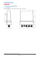
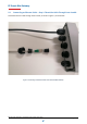
5.4 Connecting an Ethernet Cable – Step 1: Unscrew the Base and Disassemble the
Connector
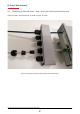
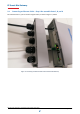
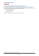
In order to connect an Ethernet cable to the PE Smart Mini Gateway, first disassemble the connector to
reveal the three parts as shown in Figure 6 below. Part A is the exterior housing for the connector, while
Parts B and C together form the interior. Please be sure to disassemble (and later to re-assemble) the
parts carefully to ensure the IP66 weatherproofing for the Gateway.
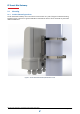
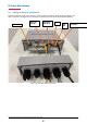
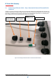
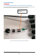
Figure 6. Connecting an Ethernet Cable to the PE Smart Mini Gateway
Part A:
Exterior Housing
Part B:
Interior Spacer
Part C:
Sub Interior Seal
Ethernet Cable