
Installation Manual


PE Smart Mini Gateway
Document No. [DOC-INS-0115-05] Date of last revision [31.05.2021]
Page 13 / 50
5.3 Wiring, Connectors, and SIM Slot
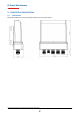
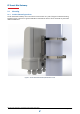
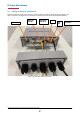
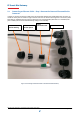
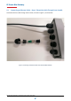
Remove the bottom cover of the device to reveal the power connector, Ethernet ports, USB port, and
other connectors. See Figure 5 for a reference to all the connectors of the PE Smart Mini Gateway.
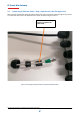
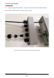
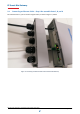
Figure 5. PE Smart Mini Gateway connectors
AC Power
Ethernet 1
(PoE IN)
Ethernet 0
(PoE OUT)
LTE External Antenna
connector
USB
SIM
Slot