
Universal Remote User Manual

16 203987 Rev A RCP2-1000 RM Remote Controller Operations Manual
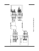
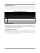
Pin # Function Description
1 Closed on Power Supply Fault Form C relay NC
2 Opened on Power Supply Fault Form C relay NO
20 Power Supply Fault Common
3 1. Standalone mode. Closed on Auxiliary Fault
2. 1:1 Redundancy Mode. Closed on Automatic switchover mode. Form C relay NC
21 1. Standalone Mode. Opened on Auxiliary Fault
2. 1:1 Redundancy Mode. Closed on Manual switchover mode. Form C relay NO
22 Auxiliary Fault\Auto-Manual Common
4 Closed on Mute. Form C Relay NC
5 Opened on Mute. Form C Relay NO
23 Mute Status Common
6 Closed on BUC Fault. Form C Relay NC
24 Opened on BUC Fault. Form C Relay NO
25 BUC Fault Common
7 Closed on High Temperature Fault. Form C Relay NC
8 Opened on High Temperature Fault. Form C Relay NO
26 High Temperature Fault Common
9 1. Standalone mode. Closed on Regulator Low Voltage Fault
2. 1:1 Redundancy Mode. Closed on HPA Standby. Form C relay NC
27 1. Standalone Mode. Opened on Regulator Low Voltage Fault.
2. 1:1 Redundancy Mode. Closed on HPA Online Mode. Form C relay NO
28 Regulator Low Voltage Fault\Standby-Online Common
10 Closed on DC Current Low Fault. Form C Relay NC
11 Opened on DC Current Low Fault. Form C Relay NO
29 DC Current Low Fault Common
12 Closed on Low Output RF Fault. Form C Relay NC
30 Opened on Low Output RF Fault Form C Relay NO
31 Low Output RF Fault Common
17 Mute/Unmute toggle input. 50mS Closure to ground to activate
35 SSPA Standby input. 50mS Closure to ground to activate
36 RCP Local/Remote toggle. 50mS Closure to ground to activate
37 Fault clear. 50mS Closure to ground to activate
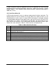
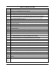
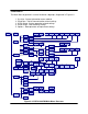
Table 2-3: Parallel I/O Pin Out
19 Ground
34, 33,
32, 18,
16, 15,
14, 13
Reserved. Make No Connection.