Operations Manual RCP2-1000 Remote Controller for Rack Mount SSPAs PARADISE DATACOM RCP2-1000 SSPA REMOTE CONTROLLER Paradise Datacom LLC 328 Innovation Blvd. State College, PA 16803 USA Email: sales@paradisedata.com 203987 Rev A Phone: (814) 238-3450 Fax: (814) 238-3829 Web: www.paradisedata.
PROPRIETARY NOTICE Paradise Datacom has made every effort to ensure that the instructions contained in this document are adequate and free of errors and omissions. Paradise Datacom will, if necessary, explain issues, which may not be covered by this document. Paradise Datacom’s liability for any errors in this document is limited to the correction of errors and the aforementioned advisory services.
Table of Contents Table of Contents ........................................................................................................ 3 Section 1: General Information .................................................................................. 7 1.0 Introduction ................................................................................................... 7 1.1 Description.................................................................................................... 7 1.
3.2.1.6 Sys Info Page 6 .................................................................................... 22 3.2.1.7 Sys Info Page 7 .................................................................................... 22 3.2.1.8 Sys Info Page 8 .................................................................................... 22 3.2.2 Panel Communication Setup Sub-Menu.................................................. 23 3.2.2.1 Protocol..................................................................
Section 5: Serial Protocol ......................................................................................... 33 5.0 Introduction ................................................................................................. 33 5.1 Remote Control - Serial Communication .................................................... 34 5.1.1 Header Packet ......................................................................................... 34 5.1.1.1 Frame Sync Word........................................
Figures Figure 1-1: Outline Drawing of RCP2-1000 RM ................................................. 7 Figure 2-1: RCP2-1000 RM Rear Panel ........................................................... 12 Figure 2-2: Cable Connections for RCP2-1000 RM ......................................... 12 Figure 2-3: Top Level Wiring Diagram .............................................................. 13 Figure 3-1: RCP2-1000 RM Front Panel...........................................................
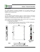
Section 1: General Information 1.0 Introduction This section provides the general information for the Paradise Datacom LLC Redundant Control Panel for Rack Mount SSPAs. This section describes the supplied equipment and safety precautions. 1.1 Description The RCP2-1000 RM controller provides control of Paradise Datacom’s Rack Mount Solid State Power Amplifiers. The RCP2-1000 RM is used for standalone or 1:1 modes of operation. An outline drawing of the RCP2-1000 is shown in Figure 1-1.
1.2 Equipment Supplied The following equipment is supplied with each unit: • • • RCP2-1000 RM Redundant System Controller (1 RU high) (2) IEC Line Cord Sets Operations Manual (203987) RCP2-1000 RM System Controller Paradise Data can provide the following optional equipment: • • Rack Slides Mating cable for Rack Mount SSPA and RCP2-1000, (Part Number L201777). 1.3 Safety Considerations Potential safety hazards exist unless proper precautions are observed when working with this unit.
1.3.2 Electrical Discharge Hazards A spark can not only create ESD reliability problems, it can also cause serious safety hazards. The following precautions should be taken when there is a risk of electrical discharge: • • • • • • Follow all ESD guidelines. Remove all flammable material and solvents from the area. All probes and tools that contact the equipment should be properly insulated to prevent electrical discharge. The work area should be secure and clear from non-essential items.
THIS PAGE LEFT INTENTIONALLY BLANK 10 203987 Rev A RCP2-1000 RM Remote Controller Operations Manual
Section 2: Installation 2.0 Introduction This section provides information for the initial inspection, installation and external connections for the RCP2-1000 RM redundant system controller. 2.1 Inspection When the unit is received, an initial inspection should be completed. First, ensure that the shipping container is not damaged. If it is, have a representative from the shipping company present when the container is opened.
2.5 Cable Connectors The RCP2-1000 RM has several I/O interconnections available on the rear panel. The controller rear panel is shown in Figure 2-1. J1 PS1 J4 SERIAL MAIN J5 SERIAL LOCAL J6 PROGRAM J7 PARALLEL I/O J9 ETHERNET Figure 2-1: RCP2-1000 RM Rear Panel The RCP2-1000 RM and a Rack Mount SSPA are linked together through 2-wire twisted pair shielded cable (such as 24 AWG twisted pair telephone cable).
Figure 2-3: Top Level Wiring Diagram RCP2-1000 RM Remote Controller Operations Manual 203987 Rev A 13
In order to achieve successful operation of the RCP2-1000 RM, the SSPA must be configured with the following parameters: Baud Rate - 9600; Serial Interface - RS485; Network Address - any. See your SSPA manual for details. Maximum cable length is 4000 feet (1.3 km). 2.5.1 Serial Port, Main (J4) A DB9 female connector serves as primary remote control interface connector.
2.5.2 Serial Port, Local (J5) A DB9 male connector serves as a serial interface with a remote SSPA. Interface parameters are set by internal RCP hardware and can't be reconfigured by user. The remote SSPA serial interface must be properly set to provide connection with the RCP unit. Table 2-2 shows the local serial port pin-out.
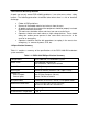
Table 2-3: Parallel I/O Pin Out Pin # Function Description 1 Closed on Power Supply Fault Form C relay NC 2 Opened on Power Supply Fault Form C relay NO 20 Power Supply Fault Common 3 22 1. Standalone mode. Closed on Auxiliary Fault 2. 1:1 Redundancy Mode. Closed on Automatic switchover mode. Form C relay NC 1. Standalone Mode. Opened on Auxiliary Fault 2. 1:1 Redundancy Mode. Closed on Manual switchover mode. Form C relay NO Auxiliary Fault\Auto-Manual Common 4 Closed on Mute.
Section 3: RCP2-1000 RM Front Panel Operation 3.0 Introduction Control of the RCP2-1000 RM can be handled through Front Panel operation, or remotely through Parallel or Serial communication to a computer. For Local (front panel) operation of the controller, simply toggle the Local/Remote button until the yellow LED indicator is illuminated on Local. When in Remote mode, the front panel buttons will be inoperative. The indicators and LCD display will still show the status of the system.
3.1.4 Liquid Crystal Display The 40 character by 2 line front panel liquid crystal display (LCD) provides a convenient method of selecting various operating parameters of the controller. All internal settings can be achieved via the LCD and menu structure. There is no need to access the interior of the controller to adjust or reconfigure hardware settings. The LCD also provides detailed information on fault conditions. 3.1.
3.2 Main Menu The Main Menu organized in several functional subgroups, diagramed in Figure 3-2. 1. Sys.Info - System Information menu sublevel 2. PanelCom - Serial Communication-related settings 3. SSPA Setup - System operation-related settings 4. Panel Setup - Fault handling settings 5. Options - Backup/restore and password settings Main Menu Sys. Info Normal Terminal 0..20dB ON/OFF 2400 4800 9600 19200 38400 Auto Manual Hot Cold 1-255 RS232/485 HPA1 HPA2 Protocol BaudRate Sys.
3.2.1 Sys Info The informative sublevel of the menu structure contains 8 pages, shown in Figure 3-3. The "Up" and "Down" keys allow the user to navigate through the pages. Pressing the "Left" and "Right" buttons will display the attenuation adjustment screen. Press "Enter" to return to the first informative page. Main Menu General System Info Menus Sys.Info Atten.(dB):XX.X Alarms:XXXXXX FrwrdRF(dBm):XX.X Ref.RF(dBm):XX.
3.2.1.2 Sys Info Page 2 This page shows a variety of alarm states which may be present within the HPA. Fault values could be "Fault", "Normal" and "N/A" • PS - power supply alarm, displays "Normal" if HPA power supplies are normally operational and "Fault" if one or more power supplies failed. • LowRF - low RF fault; • Fan - cooling system failures; • Aux. - Auxiliary fault condition; • VSWR - High Reflected power fault; • BUC - Block Up converter fault.
3.2.1.5 Sys Info Page 5 Page 5 shows settings related to the HPA 1:1 Redundant System operation. • • • • • Mode - indicates HPA operational mode. Value can be set to "1:1" for 1:1 redundancy mode and "Stdaln" for stand alone mode; Stby. - shows HPA standby state selection. "Hot" for hot standby operation (HPA retains unmuted state during standby period) and "Cold" for cold standby (HPA always mutes itself in standby mode and unmutes when switched back on-line). Ctrl. - shows HPA control style.
If the HPA controller card can not reliably communicate with an SSPA module, that module will be declared faulted. This type of fault will not affect the HPA overall summary fault state, because the controller card has the ability to track RF module faults independently. 3.2.2 Panel Communication Setup Sub-Menu This menu allows the user to select the parameters for communication between the SSPA and any remote monitor and control station. 3.2.2.1 Protocol Allows the user to select the serial protocol.
3.2.3.3 Redundancy Under this menu, the user may select the following redundancy settings for units in a 1:1 redundant mode. • • • • Switching - User may select between Auto and Manual switching. Standby Select - Allows user to select between Standby and Online states. Standby Mode - User may select either Hot Standby or Cold Standby. Unit Status - Allows user to select between HPA1 and HPA2. 3.2.3.4 Mode Selects the logical state machine used by the controller.
3.2.4.2 Fault Latch Determines the alarm reporting condition. A latched alarm will remain indicated on the front panel until the operator clears the alarm by pressing the “Enter” button. Unlatched alarms will allow the summary alarm indicator to stop displaying the alarm condition if the circumstance creating the alarm has been cleared or corrected. 3.2.4.3 Control Mode Selects between Local and Remote mode. 3.2.4.4 Panel ID Displays the serial number and firmware revision of the RCP unit. 3.2.
THIS PAGE LEFT INTENTIONALLY BLANK 26 203987 Rev A RCP2-1000 RM Remote Controller Operations Manual
Section 4: Theory of Operation 4.0 Introduction The RCP2-1000 RM was designed to provide easy Remote Monitor and Control for the Paradise Datacom Rack Mount Solid State Power Amplifier (SSPA). The unit is designed to fit a standard 1 rack unit high, 19'' wide EIA rack. The RCP2-1000 allows the user to remotely access the Rack Mount SSPA to verify its internal conditions and provide necessary adjustments. 4.
4.1.3 Voltage Regulator Output Low Fault Fault effective when remote SSPA internal voltage regulators drop output voltage below 8 volts. Fault always retains its last state when SSPA is muted. Fault threshold value is factory fixed and can't be changed by the user. Fault state signaling: Front Panel LED; Front Panel LCD; Serial Protocol Field, Form C contact closure (in Standalone mode only). 4.1.4 High Temperature Fault Fault is set when the remote SSPA's base plate reaches dangerously high temperatures.
4.1.9 RF Switch Fault In Redundant mode, the SSPA always tracks position of RF switch(es). The user is informed about the RF switch state through the front panel LCD and serial protocol. If the switch position for any reason can't reliably be determined, the SSPA declares a RF switch fault state. 4.1.10 Serial Connection Fault If serial communication can't be reliably established with remote SSPA unit, RCP21000 will declare Serial Connection fault condition.
4.2 Design Philosophy The RCP2-1000 RM remote controller was designed to achieve a new level in high reliability, maintenance free operation. A tightly integrated modular assembly approach has been used to realize a versatile controller while maintaining its user friendly operator interface. Four basic building blocks are combined in the unit: 1. Digital Core Board 2. I/O Board Assembly 3. Liquid Crystal Display 4. Front Panel Membrane Keypad Figure 4-1: Block Diagram, RCP2-1000 Digital Core Board 4.2.
The digital core board also contains the interface circuitry that allows the RCP2-1000 RM to be firmware upgradeable in the field. A block diagram of the Digital Core Board is shown in Figure 4-1. 4.2.2 I/O Board Assembly The I/O Board Assembly contains the primary (hardware) interface circuitry of the controller. It is physically attached to the Digital Core Board by two 40-pin headers. The ten (10) Form C relays and opto isolated inputs for the parallel I/O interface are included on this board assembly.
THIS PAGE LEFT INTENTIONALLY BLANK 32 XXXXXX 203987 Rev RevA- RCP2-1000 RM Remote Controller Operations Xyxyxyxy Manual
Section 5: Serial Protocol 5.0 Overview A system, which includes an RCP2-1000 and Rack Mount SSPA, can be managed from a remote computer over serial interface. To achieve this, the RCP2-1000 utilizes the same serial protocol as the Rack Mount SSPA with some minor exceptions. Requested parameter changes will not be reflected instantly on the RCP2-1000 unit because the RCP2-1000 is not a final target for the parameter changes. Some parameters are read only (all parameters under conditions tag).
5.1.1 Header Packet The Header packet is divided into 3 sub-packets which are the Frame Sync, Destination Address and Source Address packets (See Figure 5-2). Frame Sync HEADER DATA (4 Bytes) (6 - 32 Bytes) (2 Bytes) 0xAA55 Destination Address 1 Byte TRAILER (1 Byte) Source Address 1 Byte Figure 5-2: Header Packet 5.1.1.1 Frame Sync Word The Frame Sync word is a two byte field that marks the beginning of a packet. This value is always 0xAA55.
5.1.2 Data Packet The data sub-packet is comprised of 6 to 32 bytes of information. It is further divided into seven (7) fields as shown in Figure 5-3. The first six (6) fields comprise the command preamble while the last field is the actual data.
5.1.2.4 Data Tag The data tag specifies the type of internal resource of information needed to be accessed on the amplifier. The data associated with certain tags is read only. Therefore, only the “Get” command byte would be associated with these data tags. The data tag byte values are given in Table 5-2.
Table 5-3: Error Status Bytes Error Code name No Errors Data Frame Too Big Byte Value 0 No Such Data 2 Bad Value 3 Read Only 4 Bad Checksum 5 Trailer checksum not matched to calculated checksum Unrecognizable error 6 Error presented in incoming framed, but RCP unit failed to recognize it. All data aborted.
HEADER DATA (4 Bytes) (6 - 32 Bytes) TRAILER (1 Byte) FRAME CHECK Checksum 1 Bytes Figure 5-4: Trailer Sub-Packet 5.1.3.1 Frame Check The Frame Check field provides a checksum during packet transmission. This value is computed as a function of the content of the destination address, source address and all Command Data Substructure bytes. In general, the sender formats a message frame, calculates the check sequence, appends it to the frame, then transmits the packet.
Section 6: Terminal Mode The Paradise Datacom RCP2-1000 utilizes Terminal Mode Serial Protocol (TMSP) as a secondary serial protocol for Management and Control through a Remote Serial Interface. TMSP allows the user to access internal SSPA functions via a remote ASCII Terminal or its equivalent (such as HyperTerminal for Windows). TMSP is accomplished through either the RS-232 or RS-485, half duplex, serial communication link.
The following procedure will guide the user through the remote terminal setup, using the Windows 95/98 HyperTerminal software. The RCP2 must be connected to a PC com port and configured to use TMSP with 9600 Baud rate prior to setting up the PC configurations. • • Start the Windows HyperTerminal Program (default Windows location at Programs — Accessories — HyperTerminal). Enter the name of your serial connection (“Compact Outdoor SSPA” for example), and then click “Ok” button. See Figure 6-1.
• In the next window, select the following as shown in Figure 6-3: Bits per Second: 9600; Data bits: 8; Parity: None; Stop bits: 1; Flow control: none. Click “OK”. Figure 6-3: COM3 Properties window • Normally, the SSPA will not echo back characters typed by the user in Terminal window. For added security and convenience, turn on Local Echo in the HyperTerminal application. To do so, select the following from the HyperTerminal menu: File -> Properties -> Settings -> ASCII setup.
• Your PC is now configured to work with the RCP2 in Terminal mode. To establish a session with the RCP2, type “UNIT#170” Note: When using a RS485 connection, avoid using the global address (170). Instead, use the unique RCP2 address. An example of a terminal mode session shown on Figure 6-5.
Appendix A: Specifications The following pages comprise the specification sheet (203211) for the RCP2-1000 Remote Controller for Rack Mount SSPAs. For the latest revision of this document, refer to the Paradise Datacom web site (http://www.paradisedata.com).
THIS PAGE LEFT INTENTIONALLY BLANK 44 203987 Rev A RCP2-1000 RM Remote Controller Operations Manual
RCP2-1000 Remote Control Panel for Rack Mount SSPAs PARADISE DATACOM RCP2-1000 SSPA REMOTE CONTROLLER RCP2-1000 Remote Control Panel DESCRIPTION The Paradise Datacom Remote Control Panel (RCP2-1000-RM) was designed to provide easy remote monitor and control of Paradise Datacom’s Rack Mount Solid State Power Amplifier. Control of the RCP2-1000-RM can be handled through Front Panel operation, or remotely through Parallel or Serial communication to a remote computer.
RCP2-1000 Remote Control Panel for Rack Mount SSPAs RCP2-1000 FRONT PANEL DESCRIPTION Local / Remote Key Main Menu Key Enter Key PARADISE DATACOM RCP2-1000 SSPA REMOTE CONTROLLER System Identification Fault Indicators Signal Path mimic display LCD Display Auto / Manual Mode Key Display Navigation Keys GENERAL SPECIFICATIONS 2 OF 4 Characteristic Specification Configurations RCP2-1000-RM; Remote Control Panel for RM SSPA Serial Communications RS-232 / RS-485 2-wire Parallel I/O Status Outpu
RCP2-1000 Remote Control Panel for Rack Mount SSPAs Rear Panel Connectors and Pin Identification J1 PS1 J4 SERIAL MAIN J5 SERIAL LOCAL J6 PROGRAM J7 PARALLEL I/O J9 ETHERNET The RCP2-1000-RM includes two serial communications ports (J4 and J5). The Main Serial Port (J4) allows remote communication with a personal computer. The Local Serial Port (J5) allows a serial interface with a remote Rack Mount SSPA. Interface parameters are set by internal RCP hardware and cannot be reconfigured by user.
RCP2-1000 Remote Control Panel for Rack Mount SSPAs J7, Parallel I/O Connector Pin-out Pin # 1 Closed on Power Supply Fault Form C relay NC 2 Opened on Power Supply Fault Form C relay NO 20 Power Supply Fault Common 21 22 1. Standalone mode. Closed on Auxiliary Fault 2. 1:1 Redundancy Mode. Closed on Automatic switchover mode. Form C relay NC 1. Standalone Mode. Opened on Auxiliary Fault 2. 1:1 Redundancy Mode. Closed on Manual switchover mode.