
Operating Guide

24
SERVICE
Repairs
If your tool is damaged, call Panel Pro at 1-800-599-1655 or 763-755-1600 for technical advice or for the name of a
dealer near you who can service your machine.
Replacement Parts
Refer to the separate replacement parts information provided with the tool.
Alignment
The tool is aligned at the factory to a tolerance of 1/32”.
It needs realignment only if mishandled or abused, or if the motor is replaced.
Alignment consists of three steps that must be done in the following order (these steps are explained in detail
below):
1. Adjust the blade so it is parallel with the guides.
2. Adjust the blade so it will be perpendicular to the work piece.
3. Adjust the guides so they are perpendicular to front base support.
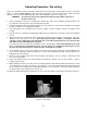
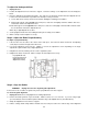
Constructing an Alignment Tool
For maximum accuracy, construct a test square to check the full movement of the saw.
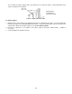
See Figure 14. Construct the square using a 6-ft metal ruler and two 4-ft metal rulers. (Using the 3-, 4-, and 5-ft
measurements assures squareness.) Drill holes and attach the rulers with pop rivets or small nuts and bolts.
Figure 14: Field Alignment Tool
Use the 6-ft ruler to check squareness of the base support. Use the 4-ft ruler to check squareness of the guide
tubes or rails. The tool also can be used as a giant square for layouts.
Step 1: Adjust the Blade Parallel to the Guides
The blade must move parallel to the guides, or tail burning may occur and the kerf will be wider than the set of the
blade. Make the following adjustment only if the blade appears to be out of alignment.
To check the blade parallelism:
1. Adjust the guides (see Steps 1 and 2 above).
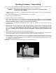
2. If the blade “heels”, or leaves burn marks on the cut, position the carriage for a crosscut and make a sample
cut. Check both sides of the cut to determine which side of the blade is causing the problem (you will need this
information for adjusting the blade).
5’
4’
3’
6’
4’ Frame Support
Line up on
36” mark.