
Operating Guide


10
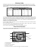
Figure 3: Overall View of Panel Pro
Attaching the Wings and the Base Support Panel
Note: Refer to Figure 3 to see what the unit will look like with the additional panels installed.
1. For ease of assembly, lay the saw frame face-up on a workbench (or across a pair of sawhorses), with the
bottom extending over the edge of the bench.
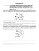
2. Attach the two wings to the sides of the saw frame. Refer to Figure 4. Attach loosely, using three 7/16”
bolts for each wing.
Fi
g
ure 4: Attachin
g
the Win
g
s and Base Su
pp
ort Panel
Attach wings to
main saw frame
(6 fasteners with
3 on each side)
Attach wings to base
support panel
(16 fasteners)
Carriage Lock
Base Support
Panel
Cord Keeper
Saw Motor Carriage
Wings
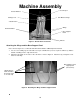
Machine Assembl
y
Wheels
Vertical Rulers
Horizontal Rulers
Counter Balance