OWNER’S MANUAL and OPERATING INSTRUCTIONS Model PRO2K If you are missing parts or have questions please contact us at: Panel Pro • 1-800-599-1655 or 763-755-1600 sales@panelpro.com www.panelpro.
A message from all of us at Panel Pro: Thank you for purchasing a Panel Pro vertical panel saw. We take pride in building these fine products in the U.S.A. Each Panel Pro product is designed to give years of dependable service. Our saws are built from the finest components we can specify, and every machine is individually assembled by our employees some of whom have been building panel saws for more than 35 years. We appreciate you purchasing our product.
CONTENTS Safety ..........................................................................................4-7 Electrical Safety......................................................................................... 7 Extension Cords ........................................................................................ 8 Short-Circuit Protection ............................................................................. 8 Warning Labels Identified…………………………………………………….. 8-9 Installation ...............
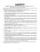
SAFETY WARNING: When using electric tools, always follow basic safety precautions to reduce the risk of fire, electric shock, and personal injury. READ AND SAVE ALL INSTRUCTIONS FOR FUTURE USE. Before use, be sure everyone using this tool reads and understands this manual as well as any labels packaged with or attached to the tool. 1. KNOW YOUR POWER TOOL. Read this manual carefully to learn your power tool’s applications and limitations as well as potential hazards associated with this type of tool. 2.
17. AVOID ACCIDENTAL STARTING. Be sure your tool is turned off before plugging it in. Do not use the tool if the power switch does not turn it on and off. Observe correct lockout/tag out procedures when performing maintenance on the tool. 18. DO NOT FORCE THE TOOL. Your tool will perform best at the rate for which it was designed. Excessive force only causes operator fatigue, increased wear, increased risk of binding or sudden breakage, and reduced control. 19.
be well supported over their entire length to avoid pinching the blade. 27. HANDLE THE COUNTERBALANCE WITH CARE. The counterbalance cable is under tension. Always attach the cable to the saw carriage before removing the cable clip. Do not pull on the cable by hand or attempt to disassemble or repair the counterbalance. Replacement counterbalances can be purchased directly from Panel Pro. 28. DO NOT USE PUSH STICKS. 29. CROSSCUTTING (VERTICAL CUTTING) MUST ALWAYS BE DONE FROM THE TOP DOWN.
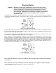
Electrical Safety WARNING: Improperly connecting the grounding wire can result in the risk of electric shock. Check with a qualified electrician if you are not sure that the outlet is properly grounded. Do not modify the plug provided with the tool. Never remove the grounding prong from the plug. Do not use the tool if the cord or plug is damaged. If damaged, have it repaired by a qualified electrician before use.
Extension Cords Grounded tools require a three-wire extension cord. As the distance from the supply outlet increases, you must use a heavier-gauge extension cord. Using extension cords with inadequately sized wire causes a serious drop in voltage, resulting in loss of power and possible tool damage. Refer to Table I on page 8 to determine the required minimum wire size.
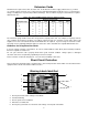
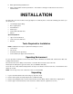
6. Blade guard warning and blade size. 7. Motor serial tag with electrical specifications. The machine serial tag is mounted on the left corner of machine frame. INSTALLATION The Panel Pro saw comes from the factory prealigned.
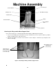
Machine Assembly Cord Keeper Counter Balance Carriage Lock Saw Motor Carriage Vertical Rulers Wings Horizontal Rulers Base Support Panel Figure 3: Overall View of Panel Pro Wheels Attaching the Wings and the Base Support Panel Note: Refer to Figure 3 to see what the unit will look like with the additional panels installed. 1. For ease of assembly, lay the saw frame face-up on a workbench (or across a pair of sawhorses), with the bottom extending over the edge of the bench. 2.
1. Attach the base support panel to the front of the unit. Attach loosely, using four 7/16” bolts to attach the support panel to each wing, and eight to attach the panel to the saw frame. 2. Tighten the fasteners. Attaching the Lower Extensions (optional accessory) Using the four 7/16” bolts provided, attach the left and right lower extensions to the base support panel. The holes are pre-set at the factory for easy positioning and installation on the base support.
Attaching the Counterbalance WARNING: To reduce the risk of injury or damage to components, do not attempt to disassemble or repair the counterbalance. Do not pull on the counterbalance cable. The cable is under strong spring force: the unit must be properly assembled before you remove the cable clip. A counterbalance is used to offset the weight of the saw. The counterbalance is shipped with the necessary hardware. Remove the two 1/4-20 x 5/8” carriage bolts, nuts, and washers from the counterbalance.
Figure 6: Attaching the Counterbalance Cable Standing Up the Tool With the help of an assistant, stand up the tool and position it in its intended operating location. Extend the rear support. If the tool is to be mounted to the floor or to a wall or post, attach it securely to avoid injury from tipping. WARNING: A freestanding saw must be located away from areas where it could be accidentally tipped over.
Rubber Stopper Pull cord keeper so it is parallel to the floor. No slack in cord. Carriage (at the bottom of the guides) Figure 8: Installing the Cord Keeper 5. Loosen the carriage lock. Allow the carriage to return to the top of the guide tubes, then lock the carriage lock. NOTE: If you discover there is too much or not enough slack in the cord, readjust as necessary.
Washer Bolt Installing the Wheel Accessory Attaching Dust Collection Kit (optional accessory) Dust Collection Kits are recommended if the tool will be used in an enclosed area. They include discharge tubing and a hose roller system to hold the outboard end of the tubing. The dust hose must be attached to an SSC Vacuum or to any high-pressure vacuum source that provides at least 90” to 110” of static pressure and 100 CFM. All machines come standard with a 2” (50.8mm) hose connection on the blade guard.
tube further in (the slot will fit around the blade), until it is as close to the work piece as possible. Tighten the clamp to hold the inner tube in place. 2. Mount the hose rollers to the top of the frame. 3. Lay the 11/2” (40.6mm) black flexible vacuum hose across the rollers, with one end to the front of the frame and one end to the back of the frame. 4. Connect the hose end that is toward the back of the frame to the vacuum (see specifications). 5.
OPERATION WARNING: The following are suggestions that give you a general idea of how a panel saw is intended to be operated. No instructions can replace common sense and experience. Be sure you and all operators have enough time and material to become familiar with the general operating characteristics of this tool, and have FULLY READ AND UNDERSTOOD all general operating and safety instructions.
Basic Operating Functions Index Pins Handle Carriage Lock Spindle Lock Blade Guard On/Off Switches Emergency Stop Switch Figure 9: Saw Motor Carriage Changing the Blade 1. Unplug the saw. Observe appropriate lockout/tag out procedures to insure the tool cannot accidentally be powered. 2. Remove the blade guard. 3. To keep the spindle from turning while you loosen the arbor bolt push the spindle lock located behind the handle. 4.
Starting and Stopping the Motor To start the motor push the green button on the control panel. To stop the motor push the red button on the control panel. The saw is also equipped with an emergency stop which is the large red button on the control panel. Rotating the Turntable on the Carriage Pull out the indexing pins, and pivot the turntable until they snap into the appropriate holes. Moving the Carriage Up or Down Use the handle on the motor.
Operating Procedure: Cross cutting A crosscut is a vertical cut that must always be done from the top to the bottom of a work piece as shown in Figure 11. (See also “General Operating Tips” above and “Limitations of the Tool” on page 16.) WARNING: To reduce the risk of injury, do not place your hands on or under the carriage or in the path of the saw blade. 1. Position the saw motor in the crosscutting position with the blade oriented vertically. Turntable,” above. See “Rotating the 2.
Operating Procedure: Rip cutting A rip cut is a horizontal cut that can be done either from the left to the right or from the right to the left, as shown in Figure 12. Rip cuts must always be done by moving the work piece in the direction of the arrow on the saw carriage. (See also “General Operating Tips” above and “Limitations of the Tool.” on page 16) WARNING: To reduce the risk of injury, ripping must always be done with the direction of the arrow on the saw. 1.
Removing the Motor: (Only to repair, maintain, or replace) WARNING: The guards on the saw motor have been modified specifically for use on the Panel Pro. NEVER use the saw motor as a hand-held unit. To remove the motor from the turntable: 1. Disconnect and lock off the power supply. 2. Remove the blade guard. 3. Remove the saw blade. 4. Support the motor by hand, and loosen the rear motor mount nut. 5. Remove the two lower nuts and bolts from the saw mounting bracket/foot. 6.
MAINTENANCE WARNING: To reduce the risk of injury, always unplug the tool before doing any maintenance. Never disassemble the tool or try to do any rewiring to its electrical system. Contact a qualified electrician for electrical repairs. Always follow lockout/tag out procedures when servicing electrical equipment. General Maintenance Keep the tool in good repair by adopting a regular maintenance program.
SERVICE Repairs If your tool is damaged, call Panel Pro at 1-800-599-1655 or 763-755-1600 for technical advice or for the name of a dealer near you who can service your machine. Replacement Parts Refer to the separate replacement parts information provided with the tool. Alignment The tool is aligned at the factory to a tolerance of 1/32”. It needs realignment only if mishandled or abused, or if the motor is replaced.
To adjust the blade parallelism: 1. Unplug the tool. 2. Position the Adjustment Tool on the base support. Lower the carriage so the Adjustment Tool overhangs the blade. 3. Place the Adjustment Tool against the blade. The entire face of the blade should contact the Adjustment Tool. If it does not, then the blade is not parallel to the work piece and you should: a. Loosen (but do not remove) the two hex-head nuts holding the indexing pin assemblies. b.
Tool. Continue to pull the carriage down: if the blade does not contact the square, or if the blade binds on the square, the guides are not aligned. Guide Tube Bracket Nuts Shown with the counterbalance removed for clarity Figure 34: Aligning the Guide Tubes To align the guides: 1. Mark the frame on the outside of the guide tube bracket for a starting reference point. Loosen the guide tube bracket nuts (Figure 34), but do not remove the bracket.