© Panduit Corp. 2014 INSTALLATION INSTRUCTIONS V00028NW Z22C-** Preconfigured Network Zone System For Technical Support: http://www.panduit.
INSTALLATION INSTRUCTIONS © Panduit Corp.
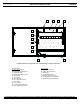
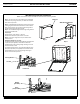
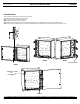
INSTALLATION INSTRUCTIONS © Panduit Corp. 2014 A V00028NW B C D L K J I H G E F Integrated Network Zone System Z22C-**configurations include the following: Pictured Above A). 24" x 24" Enclosure B). Preconfigured Back Panel C). Strain Relief Bar D). Management Slack L-rings E). Gland Plate F). Ground Bar G). 21.0" Din Rail H). Accessory Side Panels I). Fiber Spool J). 17.75" Din Rail K). LC Fiber Optic Modules (6) L). Fiber Surface Mount Box Not Pictured M). Hook and Loop Ties N).
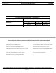
INSTALLATION INSTRUCTIONS © Panduit Corp. 2014 V00028NW Preconfigured Network Zone Z22C-** Specifications Enclosure Rating Installation Dimensions Weight UL Type 4/12 and IP66 (IEC 60529), NEMA 4X available Wall mount with optional outside-mount flange Height 24” (610 mm) 75 lbs. (34.0 kg) Width 24” (610 mm) Depth 11.
© Panduit Corp. 2014 INSTALLATION INSTRUCTIONS V00028NW SAFETY INFORMATION DISCLAIMER OF WARRANTIES AND LIMITATION OF LIABILITIES The practices contained herein are designed as a guide for use by persons having technical skill at their discretion and risk. Panduit does not guarantee any favorable results or assume any liability in connection with these instructions.
INSTALLATION INSTRUCTIONS © Panduit Corp. 2014 V00028NW Wall Mounting Bracket Installation Note: The enclosure may be mounted to the wall without the mounting brackets Latch Tool Step 1: Turn enclosure on its side with the locks orientated towards the top. Using Latch Tool, turn both locks towards each other to open door. Step 2: Install Wall Mounting Brackets into back of the enclosure aligning threaded studs on brackets to holes located in back of the enclosure.
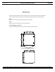
© Panduit Corp. 2014 INSTALLATION INSTRUCTIONS V00028NW Wall Mounting Enclosure may be mounted on any wall utilizing Unistrut or by drilling directly into any concrete wall. There are two mounting hole locations on the top flange and two locations at the bottom flange. Step 1: Drill holes 19.25"-22" apart horizontally and 26" apart vertically. Step 2: Mount the enlosure with the locks to the right and secure. If mounting flanges are not used: The holes in the wall will be 22.5" apart horizontally and 34.
© Panduit Corp. 2014 INSTALLATION INSTRUCTIONS V00028NW Removable Gland Plate The Gland Plate, located on the bottom of the enclosure, is removable for machining to accept bulkhead connectors or compression fittings. Remove (12) screws and (12) flat washers on the bottom of the enclosure to remove plate from the enclosure. Accommodations for incoming conduit have been supplied on the enclosure. A 1/2” conduit plug is installed in the recommended incoming power location.
INSTALLATION INSTRUCTIONS © Panduit Corp. 2014 V00028NW Reversible Door The enclosure comes with the door opening to the left. The door may be reversed to open to the right. Step 1: Remove pins from the door hinges. Step 2: Remove screws and door hinges Step 3: New Hole locations will have to be drilled or punched out. Reinstall hinges and screws on opposite side. Step 4: Turn door 180 degrees and mount to the opposite side of the enclosure. Insert the same pins to secure the door.
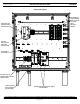
© Panduit Corp. 2014 INSTALLATION INSTRUCTIONS V00028NW Proposed Layout Din Rail Mount Copper Module (One Provided) for up to 8 CAT6 Mini-Com Modules Stratix Din Rail Mounted Switch (Not Provided) Din Rail Mount Copper Patch Box (Not Provided) Push Mounts (Provided) Electrical Circuit Breakers and Terminals (Not Provided) Industrial Switch Power Supplies (Not Provided) Panduit Uninterrupted Power Supply (Not Provided) For Technical Support: http://www.panduit.
INSTALLATION INSTRUCTIONS © Panduit Corp. 2014 Cage Removal Remove(3) #10-32 screws V00028NW Recommended Installation Instructions for Power Entry Remove plug in gland plate and replace with conduit fitting. Recommend installation of IP66 rated conduit fittings that comply with the IEC codes that are applicable to the intended application.
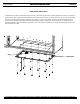
© Panduit Corp. 2014 INSTALLATION INSTRUCTIONS V00028NW Patch Cord Routing Slack tied to towel bar with hook and loop ties. (Provided) Patch cords supported by the strain relief bar and L-ring managers, routed from the switch to the patch module Fiber patch cord slack on the side mounted spool For Instructions in Local Languages and Technical Support: http://www.panduit.com/wcs/Satellite?pagename=PG_Wrapper&friendlyurl=/en/support/contact-us E-mail: tp-csdebt@panduit.com www.panduit.