
Technical Bulletin


VeriSafe
™
Absence of Voltage Tester VeriSafe
™
Absence of Voltage Tester
4 5
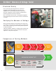
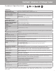
Indicator Module
• 30mm knockout, mount on exterior of enclosure
• Operate and maintain without exposure to electrical hazards
• Instruction label with operating instructions
• VS-AVT2 will have a blue faceplate while VS-AVT
will have a yellow faceplate
AVT System Cable
• Connects Isolation Module to Indicator Module
• 600V cable available in multiple lengths for easy
installation
• Replaceable with connectors on each end
• Replaceable with additional lengths
• Locking connectors on both ends
• Right angle connector at indicator module saves space
Isolation Module
• Built-in overcurrent protection prevents hazardous voltage from
reaching door
• Prevents hazardous voltage from reaching door
• Universal mounting (DIN rail or surface tabs)
• Output contacts provide ability to create alarms or
communicate with other systems
Sensor Leads
• Can be installed on line or load side of electrical disconnect
• Two leads per phase; must be physically separated
from each other
• Optimized for use with the VeriSafe
™
Insulation
Piercing Connector
• Use of ferrules is highly recommended
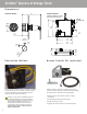
Simple Battery Replacement
• Long-life industrial battery
• Replaceable from outside the enclosure
• Interior battery compartment is fingersafe (IP20)
• No tools required
System Components
2
1
1
3
4
1
2
3
4
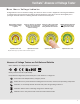
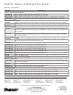
Instruction Label - VS-AVT-RL
Shown: VS-AVT
Diagnostic Label - VS-AVT-DL
Isolation module can be mounted to DIN
rail (shown) or mounted to surface using
provided mounting tabs.