
User manual
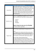
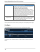
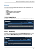
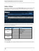
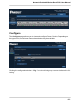
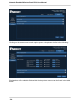
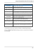
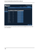
Table Of Contents
- SmartZone™ Network-Enabled M Series Rack PDU
- Equipment Overview
- Pre-Installation
- Installation
- Mounting
- Hardware
- Graphical User Interface
- Setup
- Input Sensors
- Power
Network-Enabled M Series Rack PDU User Manual
- 57 -
Configure Power Circuits
Circuit Name The name of the chosen circuit.
Upper Control Limit The value at which an Upper Control alarm will be issued.
Upper Warning Limit
The value at which an Upper Warning alarm will be
issued.
Lower Warning Limit
The value at which a Lower Warning alarm will be issued.
Lower Control Limit The value at which a Lower Control alarm will be issued.
Trap Enabled
When the box is checked, enables the unit to send traps
relating to the corresponding limit.
Repeat Timer
This entry (in seconds) determines how often repeat traps
will be generated if the error condition persists.
Upper Threshold Limit
The value at which a “High” alarm will be issued. The
default value is 1.00. This value applies to Power Factor
only.
Lower Threshold Limit
The value at which a “Low” alarm will be issued. The
default value is 0.01. This value applies to Power Factor
only.
The drop-down menus can be closed by clicking the corresponding arrows again.
Clicking the Monitor Trap Text button brings up screen to customize the text displayed
for each trap type.