
User manual
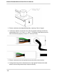
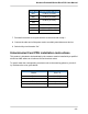
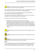
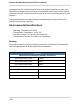
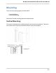
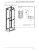
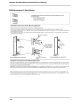
Table Of Contents
- SmartZone™ Network-Enabled M Series Rack PDU
- Equipment Overview
- Pre-Installation
- Installation
- Mounting
- Hardware
- Graphical User Interface
- Setup
- Input Sensors
- Power
Network-Enabled M Series Rack PDU User Manual
- 13 -
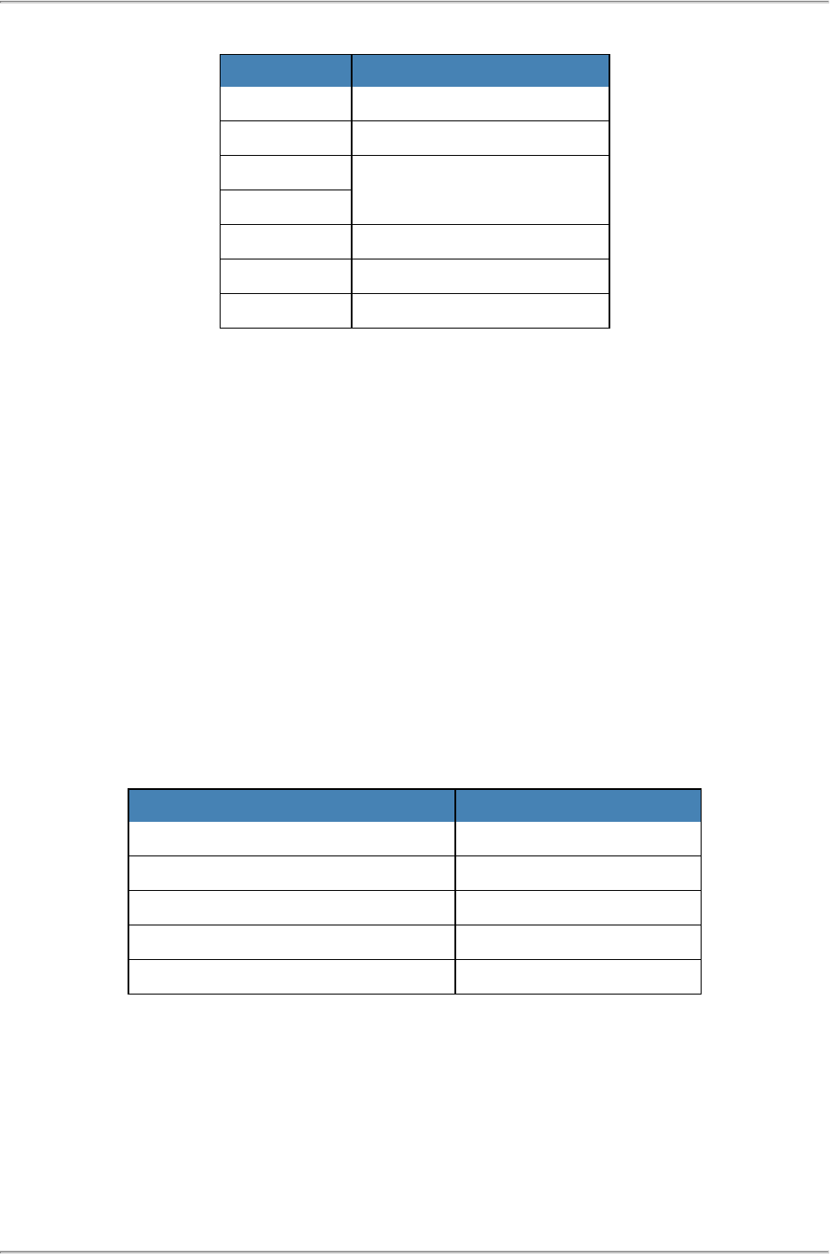
Gland Size Grommet Cap Torque
M16 1.5 N-m (13 in-lb.)
M20 3.0 N-m (27 in-lb.)
M25
4.0 N-m (35 in-lb.)
M32
M40 15 N-m (132 in-lb.)
M50 20 N-m (177 in-lb.)
M63 30 N-m (266 in-lb.)
7. Re-install removable cover plate with the screws removed in step 1.
8. Connect the other end of the power cord to a suitably rated disconnect device.
9. Switch utility circuit breaker “On”.
Unterminated Cord PDU installation instructions
This product is intended to be hardwired by the customer must be installed by a qualified
electrician AND adhere to all national & local electrical codes.
To install, match the corresponding conductor color to the matching phase in your facil-
ity. Reference the color guide below:
Conductor Insulation Color Line Number / Phase
Brown Line1 / X
Black Line 2 / Y
Grey Line 3 / Z
Blue Neutral
Green (may include Yellow stripe) Ground