
User Manual


Table Of Contents
- TA BLE OF CON TENTS
- In stal la tion and Op er a tion
- Un packing Your Printer 2
- Getting To Know Your Printer 3
- In stal la tion 4
- Step 1 - At tach Power 4
- Step 2 - At tach In ter face Ca ble 5
- Step 3 - Load Me dia 6
- Step 4 - AutoSense 12
- Using Ex ter nal Media 13
- Ther mal Trans fer Rib bon Loading 14
- Ap pen dix - Trou ble shooting 17
- Printer Main te nance 18
- Se rial In ter face Ca ble Wiring 19
- In stal la tion and Op er a tion
- test.pdf
- TA BLE OF CON TENTS
- In stal la tion and Op er a tion
- Un packing Your Printer 2
- Getting To Know Your Printer 3
- In stal la tion 4
- Step 1 - At tach Power 4
- Step 2 - At tach In ter face Ca ble 5
- Step 3 - Load Me dia 6
- Step 4 - AutoSense 12
- Feeding Ex ter nal Media 13
- Ther mal Trans fer Rib bon Loading 14
- Ap pen dix - Trou ble shooting 16
- Printer Main te nance 17
- Se rial In ter face Ca ble Wiring 18
- In stal la tion and Op er a tion
- TA BLE OF CON TENTS
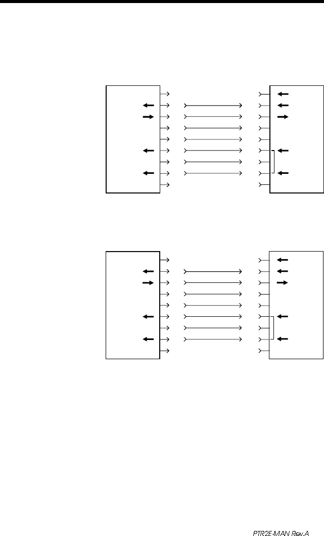
Serial Interface
Cable Wiring
The figure below displays the cable wiring
required to use the printer's RS-232 serial
interface.
18
N/C
RxD
TxD
DTR
GND
DSR
RTS
RI
CTS
PrinterHost
11
22
33
44
55
66
77
88
99
DB-9
Pin #
DB-9
Pin #
Female DB-9 to Male DB-9
Cable P/N 300017-006 (6') or 300017-010 (10')
N/C
RxD
TxD
DTR
GND
DSR
RTS
RI
CTS
PrinterHost
18
23
32
420
57
66
74
85
922
DB-25
Pin #
DB-9
Pin #
Female DB-25 to Male DB-9
Cable P/N 300018-006 (6')
*+5 volts at 150 mA for external device (e.g. KDU or scanner)
+5 Volts*
TxD
RxD
N/C
GND
RDY
N/C
N/C
RDY
+5 Volts*
TxD
RxD
N/C
GND
RDY
N/C
N/C
RDY