
Installation Manual
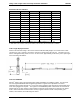
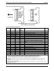
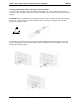
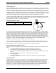
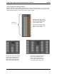
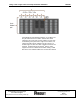
Table Of Contents

10Gig™ SFP+ Copper Cable Assembly Installation Guidelines PN533B
Panduit Corporation, 2011 Page 3 of 7
SFP+ Cable Assembly Connector Pin Out
SFP+ Pin Assignment Definitions
Contact
Logic(1)
Symbol
Power
Sequence
Order
Description
Note
Case
Case
Note 2
Module case
2
1
VeeT
1
st
Module transmitter ground
3
2 LVTTL-O Tx_fault 3
rd
Module transmitter fault (N/A) 4
3
LVTTL-I
Tx_disable
3
rd
Transmitter disable (N/A)
4
4
LVTTL-I/O
SDA
3
rd
2-wire serial interface data line, same as MOD-DEF2
5
5
LVTTL-I/O
SCL
3
rd
2-wire serial interface clock, same as MOD-DEF1 5
6
Mod_ABS
3
rd
Module absent, connected to VeeT or VeeR in module
6
7
LVTTL-I
RSO
3
rd
Rate select 0, optionally controls SFP+ receiver (N/A)
4
8 LVTTL-O Rx_LOS 3
rd
Receiver loss of signal indication (N/A) 4
9 LVTTL-I RS1 3
rd
Rate select 1, optionally controls SFP+ transmitter
(N/A)
4
10
VeeR
1
st
Module receiver ground
3
11
VeeR
1
st
Module receiver ground
3
12
CML-O
RD-
3
rd
Receiver inverted data output
13
CML-O
RD+
3
rd
Receiver non-inverted data output
14
VeeR
1
st
Module receiver ground
3
15
VccR
2
nd
Module receiver 3.3V supply
16
VccT
2
nd
Module transmitter 3.3V supply
17
VeeT
1
st
Module transmitter ground
3
18
CML-I
TD+
3
rd
Transmitter non-inverted data output
19
CML-I
TD-
3
rd
Transmitter inverted data output
20
VeeT
1
st
Module Transmitter Ground
3
Notes:
1. Labeling as Input (I) and Output (O) are from perspective of the module (cable connector)
2. The case makes electrical contact to the host cage before any board edge contacts are made
3. The module signal grounds, VeeR and VeeT, should be isolated from the module case
4. Tx-fault, Tx_disable, rate select, and loss of signal functions are not implemented in passive copper cable
assemblies
5. SDA and SCL are the data and clock pins for the I2C interface to the EEPROM on board the module. The
registers are defined in SFF-8472.
6. Mod_ABS is an output pin to indicate if the module is present in the host port It is connected to ground in the
module (cable connector)
SFP Connector Module Contact Assignments
(Top and Bottom are backwards)