Operating Instructions DLPTM Based Projector Commercial Use PT-D7700E PT-DW7000E ON POWER DEUTSCH ENGLISH Model No. OFF AUTO SETUP RGB RGB VIDEO S-VIDEO MENU FREEZE 1 AUX 2 SHUTTER SHUT PAGE UP ENTER FRANÇAIS PAGE DOWN ON SCREEN 1 STD 2 4 FUNC 1 5 7 LENS 8 OSD 3 SYSTEM SEL D.
Dear Panasonic Customer: This instruction booklet provides all the necessary operating information that you might require. We hope it will help you to get the most performance out of your new product, and that you will be pleased with your Panasonic DLPTM based projector. The serial number of your product may be found on its back. You should note it in the space provided below and retain this booklet in case service is required.
IMPORTANT: THE MOULDED PLUG (U.K. only) FOR YOUR SAFETY, PLEASE READ THE FOLLOWING TEXT CAREFULLY. ENGLISH This appliance is supplied with a moulded three pin mains plug for your safety and convenience. A 13 amp fuse is fitted in this plug. Should the fuse need to be replaced, please ensure that the replacement fuse has a rating of 13 amps and that it is approved by ASTA or BSl to BS1362. Check for the ASTA mark or the BSl mark on the body of the fuse.
Contents IMPORTANT SAFETY NOTICE ..................................2 Precautions with regard to safety ............................5 Accessories ................................................................7 Precautions on handling ...........................................8 Examples of system expansion................................9 Name and function of parts.....................................10 Remote control ................................................................
Precautions with regard to safety WARNING If a problem occurs (such as no image) or if you notice smoke or a strange smell coming from the projector, turn off the power and disconnect the power cord from the wall outlet. • Do not continue to use the projector in such cases, otherwise fire or electric shocks could result. • Check that no more smoke is coming out, and then contact an Authorized Service Centre for repairs. • Do not attempt to repair the projector yourself, as this can be dangerous.
Precautions with regard to safety Do not place liquid containers on top of the projector. • If water spills onto the projector or gets inside it, fire or electric shocks could result. • If any water gets inside the projector, contact an Authorized Service Centre. Do not insert any foreign objects into the projector. • Do not insert any metal objects or flammable objects into the projector or drop them onto the projector, as doing so can result in fire or electric shocks.
Do not look into the lens while the projector is being used. • Strong light is emitted from the projector’s lens. If you look directly into this light, it can hurt and damage your eyes. Do not bring your hands or other objects close to the air outlet port. • Heated air comes out of the air outlet port. Do not bring your hands or face, or objects which cannot withstand heat. Do not use the old lamp unit. • The lamp section may break.
Precautions on handling Precautions on transport The projection lens is susceptible to vibrations and impacts. Be sure to always remove the lens during transport. Precautions on installation Be sure to observe the following precautions when installing the product. Avoid installing the product in a place exposed to vibrations or impacts.
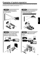
Examples of system expansion The projector is provided with a number of terminals and optional accessories to enable various system expansions. Both input and output are provided to all terminals on the main unit. The following are some examples of system expansion: System 2 Stacking two projectors with the stacking brackets can double the picture brightness. The optional high- or low-ceiling mount bracket flexibly fits the projector in individual site conditions.
Name and function of parts Remote control ON POWER OFF AUTO SETUP RGB RGB VIDEO S-VIDEO MENU FREEZE 1 AUX 2 SHUTTER SHUT PAGE UP ENTER PAGE DOWN ON SCREEN 1 STD 2 4 FUNC 5 OSD 3 SYSTEM SEL D.ZOOM 1 6 BRIGHT 7 LENS 8 ASPECT LIGHT ID ALL Numetric < When the operation mode selector set to Projector > is Remote control operation indicator lamp The lamp flashes when any remote control button is pressed.
P FF ct /O je N O R SE LA T T H LIG 8 R B S N LE 5 C N FU 1 E E R 1 4 D T S 2 C S O N N W O D P U PA GE R TE EN 7 6 IG H L E S M O SY STE M N 3 D O S .
Name and function of parts Front and side of the projector AC IN terminal (page 33) Connect the supplied line power cord into this receptacle. Do not connect any other cable to this socket. MAIN POWER switch (page 33) Use this switch to turn on “I” and off “o” the commercial line power applied to the projector. Burglar lock Attach a commercial burglar prevention cable (e.g., from Kensington) to this lock port. It is compatible with the Microsaver Security System from Kensington.
Rear view of the main unit Controls on rear panel AUTO SETUP RGB 1 RGB 2 VIDEO S-VIDEO AUX SHUTTER LENS Lamp unit cover The lamp unit is housed. Remote control receiver window (rear) (page 15) This also receives the signal beam coming from the remote control. POWER ON (I) button (page 33) Turns on the power. POWER OFF ( ) button (page 34) Turns off the power. AUTO SETUP button (page 37) Pressing this button while projecting an image automatically corrects the picture positioning on the screen.
Name and function of parts Side-mounted connection terminals RS-232C (G) / RS-422 (R) IN OUT REMOTE 1 S-VIDEO IN IN OUT R/PR S-VIDEO IN terminal (pages 22 and 23) An input terminal for S-video signals (MIN4-pin DIN). This terminal complies with S1 signals and automatically toggles between 16:9 and 4:3 according to the size of input signals. VIDEO IN terminal (page 23) An input terminal for video signals. (BNC) VIDEO OUT terminal (page 23) An output terminal (active through) for video signals.
Using the remote control unit Loading dry cells When loading supplied AA dry cells into the battery compartment of the remote control, make sure that their polarities are correct. 1. Open battery compartment lid. Open the lid in the order of steps and . Effective range of remote control operation The remote control should normally be aimed at either the front or rear remote control receiver window on the projector (figure 1).
Using the remote control unit Setting projector ID number to remote control Every projector has its ID number and the ID number of the controlling projector must be set to the remote control in advance so that the user can operate the remote control. The ID number of the projector is set to “ALL” on shipping, and use the ID ALL button of the remote control when using only a single projector. Procedure of ID setting Change the position of the operation mode selector switch to “Computer”.
Using the remote control as a PC mouse Operation mode selector switch Put the knob to the Computer position. • ENTER button Pressing the front, rear, left and right edges of the button moves the mouse cursor up, down, left and right. • Right click ( ) button This button can be used as the right mouse button. • Left click ( ) button This button can be used as the left mouse button. • PAGE UP button This button can be used as the Page Up button on the PC keyboard.
Installation Adjusting the leveling feet The four leveling feet mounted at the bottom of the projector are level-adjustable (0 mm–33 mm) which can be used when the floor surface is not horizontal. < Front > < Side > Leveling feet Projection scheme This projector can use any of the four projection schemes shown at right. Select the scheme that best suits your particular installation location. Select the most suitable scheme to the situation of your location.
Projection distances by the type of projection lenses (optional) Every type of optional projection lenses has a different projection distance to achieve the same screen size. Select and purchase a projection lens most suitable to the size of your location referring to the following tables and the projection distances by the type of projection lenses on the next page.
Installation Projection distances by the type of projection lenses (optional) (continuing) Projection distances by the type of projection lenses (for PT-DW7000E) • For the screen aspect ratio of 16:9 Units: m Projection distance (L) Zoom lens Screen dimensions FixedScreen focus lens size Effective Effective ET-D75LE1 ET-D75LE3 ET-D75LE4 ET-D75LE8 ET-D75LE2 (2.0-3.0 :1) (inch) height (3.0-5.0 :1) (5.0-8.0 :1) (8.0-15.0 :1) (1.5-2.
If the projector is used with a screen size not listed in this manual, check the diagonal dimension (inch) of your screen and calculate the projection distance using the following formulas. Calculation formulas for projection distance by lens types (for PT-D7700E) ET-D75LE1 (1.5–2.0 :1) ET-D75LE2 (2.0–3.0 :1) Zoom lens ET-D75LE3 (3.0–5.0 :1) ET-D75LE4 (5.0–8.0 :1) ET-D75LE8 (8.0–15.0 :1) Fixedfocus lens ET-D75LE5 (0.8:1) Aspect ratio Projection distance (L) formula 4:3 Minimal distance: L=0.
Connection Before starting connection Before connection, read carefully the instruction manual for the device to be connected. Turning off the power switch of the devices before connecting cables. If any connection cable is not supplied with the device, or if no optional cable is available for connection of the device, prepare a necessary system connection cable to suit the device. Video signals containing too much jitter may cause the images on the screen to randomly wobble or wafture.
Example of connecting with VIDEO devices Video deck (TBC built-in) Colour monitor RS-232C (G) / RS-422 (R) IN OUT REMOTE 1 S-VIDEO IN VIDEO IN OUT R/PR RS-232C (G) / RS-422 (R) IN REMOTE 2 G/Y ENGLISH Control PC RGB 1 IN B/PB SYNC/HD OUT SERIAL RGB 2 IN VD Red (connected to PR terminal) Blue (connected to PB terminal) Green (connected to Y terminal) Video deck (TBC built-in) High-vision video deck Attention • When connecting with a video deck, be sure to use the one with a built-in time b
Connection Example of connecting with personal computers Control PC PC PC I/F RS-232C (G) / RS-422 (R) IN OUT REMOTE 1 S-VIDEO IN OUT IN G/Y OUT R/PR G/Y SERIAL RGB 2 IN VD RS-232C (G) / RS-422 (R) IN REMOTE 2 VIDEO IN OUT RGB 1 IN B/PB SYNC/HD RS-232C (G) / RS-422 (R) IN OUT REMOTE 1 S-VIDEO IN R/PR RS-232C (G) / RS-422 (R) IN REMOTE 2 VIDEO RGB 1 IN B/PB SYNC/HD OUT SERIAL RGB 2 IN VD Attention • When the main power of the main unit is turned off, also turn off the power of
Example of connecting with the signal selector Notebook computer Video deck (TBC built-in) Control PC Signal selector POWER OFF 5 VP 6 ON/OFF Signal Selector TW-SWS G/Y ENGLISH R/PR 4 RS-232C (G) / RS-422 (R) OUT IN REMOTE 2 OUT INPUT SELECT 3 DVD player VIDEO IN 2 OFF RS-232C (G) / RS-422 (R) OUT IN REMOTE 1 S-VIDEO IN 1 ON Digital broadcasting tuner RGB 1 IN B/PB SYNC/HD SERIAL RGB 2 IN VD OUT RS-232C (G) / RS-422 (R) OUT IN REMOTE 1 S-VIDEO IN Note VIDEO IN OUT R/PR
Installation of input module (optional) Installing the input module Types of the input modules (optional) Prepare beforehand an input module (optional) compatible with the input signals of the system. Module SD-SDI input module HD/SD-SDI input module Module model No. ET-MD77SD1 ET-MD77SD3 Terminal BNC input x 1 BNC output x 1 SMPTE259M compliant : 480i, 576i RJ-45 input x 1 10BASE-T/100BASE-TX BNC input x 1 BNC output x 1 SMPTE259M compliant : 480i, 576i SMPTE292M compliant : 720/60p, 720/59.
Procedure of installation Disconnect the power before installing the input module. Slot cover ENGLISH Remove the slot cover. Remove 2 screws. Insert the input module. Input module Slot Fix the input module. Register the input signal. This projector needs to register the type of input signal after the installation of the input module. (For details on the registration of the input signals, refer to pages 38–41.) Tighten the two screws.
Installation of input module (optional) Connecting signals to the input module When installing the projector, it is necessary to connect signals to the input module in accordance with the connecting equipment. Refer to the following diagram to establish proper signal connection.
Connecting the signal to the SD-SDI input module SD-SDI input module (optional) ET-MD77SD1 (for 480i/576i) IN SERIAL SD-SDI signal OUT LAN SD-SDI signal output (active through) ENGLISH SD-SDI Module ET-MD77SD1 LAN terminal (10BASE-T / 100BASE-TX) For details on the network function, refer to page 82. Business digital VCR • Insert the input module suitable for the input signal specifications. • Normally, use SYSTEM SELECTOR in “AUTO”.
Installation of input module (optional) Connecting the signal to the HD/SD-SDI input module HD/SD-SDI input module (optional) ET-MD77SD3 (for HD/SD) HD/SD-SDI Module ET-MD77SD3 IN SERIAL HD-SDI or SD-SDI signal OUT LAN HD-SDI or SD-SDI signal output (active through) LAN terminal (10BASE-T / 100BASE-TX) For details on the network function, refer to page 82. Business digital VCR • Insert the input module that meets the input signal specifications. • Normally, use SYSTEM SELECTOR in “AUTO”.
Connecting signals to the DVI-D input module DVI-D input module (optional) ET-MD77DV DVI-D IN DVI-D signal PC with DVI output • Pin assignments and signal names of DVI-D input terminal are listed in the table at right. LAN LAN terminal (10BASE-T / 100BASE-TX) For details on the network function, refer to page 82. DVD player or high-vision video deck equipped with DVD/HDMI terminal Pin No. Signal T.M.D.S data 2– T.M.D.S data 2+ T.M.D.
How to install and remove the projection lens (optional) How to install the projection lens How to remove the projection lens While pressing the lock button on the projection lens cover, pull the cover forward to remove it. While pressing the lock button on the projection lens cover, pull the cover forward to remove it. Lens cover’s lock button Pull and remove the dustproof sheet on the back of the projection lens cover.
Projection AUTO SETUP ON POWER AUTO SETUP RGB VIDEO S-VIDEO MENU FREEZE 1 RGB 1 RGB 2 VIDEO S-VIDEO OFF RGB AUX 2 SHUTTER AUX SHUT SHUTTER PAGE UP - ENTER LENS MENU ENTER PAGE DOWN ON SCREEN 1 STD 2 4 FUNC 5 OSD 3 SYSTEM SEL D.ZOOM 6 BRIGHT 7 - LENS 8 ASPECT LIGHT ID ALL Numetric Powering up the projector Connect the supplied power cable. (220 V–240 V~, 50 Hz/60 Hz) Press the “I” marked side of the MAIN POWER switch to turn on the power.
Projection ON AUTO SETUP POWER OFF AUTO SETUP RGB RGB VIDEO S-VIDEO MENU FREEZE 1 AUX 2 SHUTTER RGB 1 RGB 2 VIDEO S-VIDEO AUX SHUT SHUTTER PAGE UP ENTER LENS MENU ENTER PAGE DOWN ON SCREEN 1 STD 2 4 FUNC 5 OSD 3 SYSTEM SEL D.ZOOM 1 6 BRIGHT 7 LENS 8 9 NEXT ASPECT LIGHT ID ALL Computer Numetric CONTRAST 0 USER ID SET LASER ON/OFF Projector Powering off the projector Press the POWER OFF “ ” button. Select “OK” with or button and press the ENTER button.
How to adjust the lens How to adjust the lens focus, lens zoom and lens shift (optical shift) If the focusing, zooming or positioning of the image projected on the screen is not successful, even though the projector is properly positioned against the screen, you can adjust the focus, the zoom, or the vertical or horizontal position of the image. Press the LENS button on the remote control or on the control panel of the main unit.
How to adjust the lens How to adjust the lens for addressing unevenness of focusing If the image is out of focus in any portion of the screen, adjust the lens by turning the adjustment screws to obtain evenness of focusing. Lens bracket Fixing screws a Remove the lens cover and lens (Refer to page 32). Loosen the three fixing screws that secure the lens bracket about two turns. • Tool to be used : Allen hex socket driver or Allen wrench (2.5-mm diagonal hexagon) Install the lens removed in step .
Automatic adjustment (AUTO SETUP) Automatic adjustment function adjust the resolution, clock phase and image position automatically when dotsstructured analogue RGB signals such as computer signal are supplied. (Automatic adjustment is not available if signals or moving images other than analogue RGB signals are supplied.) It is recommended to supply images with a bright white frame at the outermost periphery containing characters etc.
Registration of input signal data The input signal data must be registered because it is not registered on shipment of the projector. Registration of new data When a new signal is supplied, press the “MENU” button on the remote control or operating section of the main unit. When its data has been registered, the MAIN MENU screen is displayed. Note • The data of 96 input signals can be registered. • The signals supporting the installed input module are input and their data registered.
Press the “ENTER” button. RENAME NAME: MEMORY NO: S.S.NO: INPUT NO: fH: fV: SYNC. STATE: :NEXT FIGURE The RENAME screen will be displayed. SVGA72-A2 A2 –– RGB1 48.08kHz 72.17Hz H(POS) V(POS) :FONT SELECT ENTER:SET MENU:ESC Select each character with the and buttons, and set the character or number with the and buttons (press the “STD” button to clear the name which is automatically displayed). After the signal has been renamed, press the “ENTER” button.
Registration of input signal data Sub memory The projector is provided with a sub memory function to register plural pieces of image adjustment data even they are determined to be the same signal by the frequency and form of the synchronization signal source. Use this function when the user needs adjustment of picture quality such as aspect switching and white balance using the same signal source.
On-screen indications Input switching / signal switching This shows the registered signal name on the status screen for signal switching. NAME: MEMORY NO: S.S. NO: INPUT NO: RGB A1 (1-2) ––– RGB1 ENGLISH Details of registered signal REGISTERED SIGNAL STATUS NAME: MEMORY NO: S.S.NO: INPUT NO: fH: fV: SYNC. STATE: SXGA60-A1 ?? (1-2) ––– RGB1 48.00kHz 60.00Hz H(POS) V(POS) ENTER:CHANGE NANE The designation can be set by the sub memory items. MEMORY NO: A1 (1-2) displays the sub memory number.
Using the FREEZE function Pressing the “FREEZE” button of the remote control switches between a still image and a motion image. Still image Motion image Using the SHUTTER function If the projector is not used for a certain period of time during the meeting intermission, for example, a shutter mode is available that allows the user to hide images temporarily. Press the “SHUTTER” button of the remote control or the main unit. The image is turned off. Press the “SHUTTER” button again.
On-screen menus Structure of menu screens Menus are extensively used for configuring, adjusting or reconfiguring the projector.
On-screen menus Basic operations on menu screen • When the “MENU” is on the screen, pressing the “MENU” button returns to the previous page. • When the MAIN MENU is on the screen, pressing the “MENU” button clears all menus from the screen. Press the “MENU” button. The MAIN MENU appears on the screen.
Adjusting the picture Switching the picture mode The user can switch to the desired picture mode suitable for the image source and the environment in which this projector is used. Press the “MENU” button. MAIN MENU PICTURE POSITION ADVANCED MENU LANGUAGE OPTION TEST PATTERN SIGNAL LIST SECURITY The MAIN MENU screen will be displayed. Select “PICTURE” with the buttons. :MENU SELECT ENTER:SUB MENU Press the “ENTER” button. DYNAMIC 50 30 DEFAULT 2.
Adjusting the picture The desired picture can be obtained by following the procedure below. Adjusting Contrast / Bright / Colour / Tint Adjustment procedure – to adjust picture (colour intensity) Press the “MENU” button. MAIN MENU PICTURE POSITION ADVANCED MENU LANGUAGE OPTION TEST PATTERN SIGNAL LIST SECURITY The MAIN MENU screen will be displayed. Select “PICTURE” with the buttons. :MENU SELECT ENTER:SUB MENU PICTURE PICTURE MODE COLOR TINT COLOR TEMP.
Registering the picture mode settings as presettings The screen settings which have been adjusted by following the adjustment procedure (on the previous page) can be registered. Press the “MENU” button. MAIN MENU PICTURE POSITION ADVANCED MENU LANGUAGE OPTION TEST PATTERN SIGNAL LIST SECURITY The MAIN MENU screen will be displayed. Select “PICTURE” with the buttons. :MENU SELECT ENTER:SUB MENU Press the “ENTER” button. DYNAMIC 50 30 DEFAULT 2.
Adjusting the picture DYNAMIC IRIS setting Pictures with the optimum contrast will be displayed by automatically providing aperture compensation and signal compensation to suit the pictures concerned. DYNAMIC IRIS 1 2 3 USER OFF DYNAMIC IRIS AUTO IRIS MANUAL IRIS DYNAMIC GAMMA 2 OFF 1 Press the buttons on the “PICTURE” screen to select “DYNAMIC IRIS”. Select the "DYNAMIC IRIS" setting with the buttons.
Adjusting the colour temperature Adjustment procedure (to be performed while projecting the signals to be adjusted) Press the “MENU” button. MAIN MENU PICTURE POSITION ADVANCED MENU LANGUAGE OPTION TEST PATTERN SIGNAL LIST SECURITY Select “PICTURE” with the buttons. Press the “ENTER” button. DYNAMIC 50 30 DEFAULT 2.2 32 32 6 2 1 The PICTURE screen will be displayed. Select “COLOR TEMP.” with the buttons. Select the desired setting from below with the buttons.
Adjusting the picture Sharpness / Gamma / Noise reduction Procedure of adjustment Press the “MENU” button. MAIN MENU PICTURE POSITION ADVANCED MENU LANGUAGE OPTION TEST PATTERN SIGNAL LIST SECURITY PICTURE PICTURE MODE COLOR TINT COLOR TEMP. GAMMA CONTRAST BRIGHT SHARPNESS NOISE REDUCTION DYNAMIC IRIS The MAIN MENU screen will be displayed. Select “PICTURE” with the buttons. Press the “ENTER” button. DYNAMIC 50 30 DEFAULT 2.2 32 32 6 2 1 The PICTURE screen will be displayed.
Adjusting the position Desired position can be achieved by following the procedure below. Shift adjustment This function allows the user to adjust the picture position vertically or horizontally if the position of the image projected on the screen is displaced when the projector is properly positioned against the screen. Procedure of adjustment Press the “MENU” button.
Adjusting the position Size adjustment Procedure of adjustment Press the “MENU” button. MAIN MENU PICTURE POSITION ADVANCED MENU LANGUAGE OPTION TEST PATTERN SIGNAL LIST SECURITY The MAIN MENU screen will be displayed. Select the “POSITION” with the buttons. :MENU SELECT ENTER:SUB MENU POSITION SHIFT SIZE CLOCK PHASE KEYSTONE Press the “ENTER” button. DEFAULT 0 The POSITION screen will be displayed. Select “SIZE” with the buttons. Using the buttons, select the size mode.
• DEFAULT: Pictures are displayed without changing the aspect ratio of the input signals. • THROUGH: Pictures are displayed without changing the resolution of the input signals. • ZOOM: Pictures can be displayed in various magnifications. The user can magnify the pictures with the magnification ranging from 50% to 999%, and the fiducial point is set on the top left of the screen. • 16:9 (D7700E only): Pictures are displayed in the aspect ratio of 16:9.
Adjusting the position Keystone distortion correction Keystone distortion can be corrected only along either horizontal bound of the picture. Procedure of adjustment Press the “MENU” button. MAIN MENU PICTURE POSITION ADVANCED MENU LANGUAGE OPTION TEST PATTERN SIGNAL LIST SECURITY The MAIN MENU screen will be displayed. Select the “POSITION” with the buttons. :MENU SELECT ENTER:SUB MENU POSITION SHIFT SIZE CLOCK PHASE KEYSTONE Press the “ENTER” button.
How to use ADVANCED MENU DIGITAL CINEMA REALITY Increase the vertical resolution when the PAL (or SECAM) 576i signal input or the NTSC 480i signal input is applied. Procedure of adjustment Press the “MENU” button. MAIN MENU PICTURE POSITION ADVANCED MENU LANGUAGE OPTION Note Select “ADVANCED MENU” with the buttons. Press “ENTER” button. AUTO SMPTE The ADVANCED MENU screen will be displayed. Select “DIGITAL CINEMA REALITY” with the buttons.
How to use ADVANCED MENU Blanking adjustment Blanking adjustment fine-tunes the images projected by the video deck or other devices when the noise appears on the edges of the screen or if a part of the image lies slightly offscreen. Procedure of adjustment Press the “MENU” button. MAIN MENU PICTURE POSITION ADVANCED MENU LANGUAGE OPTION TEST PATTERN SIGNAL LIST SECURITY The MAIN MENU screen will be displayed. Select the “ADVANCED MENU” with the buttons.
Adjusting the input resolution Input resolution adjustment achieves the best image when the screen flickers or halo is observed around the contour. Procedure of adjustment Press the “MENU” button. MAIN MENU PICTURE POSITION ADVANCED MENU LANGUAGE OPTION TEST PATTERN SIGNAL LIST SECURITY The MAIN MENU screen will be displayed. Select the “ADVANCED MENU” with the buttons. :MENU SELECT ENTER:SUB MENU Press the “ENTER” button.
How to use ADVANCED MENU Adjusting the clamp position Use the clamp position adjustment to achieve the optimal value when dark areas of the image are crushed or displayed in green. Procedure of adjustment Press the “MENU” button. MAIN MENU PICTURE POSITION ADVANCED MENU LANGUAGE OPTION TEST PATTERN SIGNAL LIST SECURITY The MAIN MENU screen will be displayed. Select “ADVANCED MENU” with the buttons.
Edge blending adjustment This projector has the function to hide the seams for multi-screens. Procedure of adjustment Press the “MENU” button. MAIN MENU PICTURE POSITION ADVANCED MENU LANGUAGE OPTION TEST PATTERN SIGNAL LIST SECURITY Select the “ADVANCED MENU” with the buttons. Press the “ENTER” button. AUTO SMPTE The ADVANCED MENU screen will be displayed. Select “EDGE BLENDING” with the buttons. Select “OFF”, “ON” or “USER” with the buttons.
How to use ADVANCED MENU Edge blending adjustment (continuing) BRIGHT ADJUST BRIGHT INSIDE BRIGHT OUTSIDE UPPER LOWER LEFT RIGHT Select the “BRIGHT ADJUST” with the buttons. 6 6 Press the ENTER button. 0 0 0 0 Projection range The BRIGHT ADJUST screen will be displayed. Edge blending width (right) BRIGHT adjustment (right) Marker BRIGHT INSIDE Note 60 BRIGHT OUTSIDE Select the “BRIGHT INSIDE” with the buttons. Adjust the compensation value (0-255) with the buttons.
Raster position When the whole area where the input picture can be displayed is not used, the picture can be moved to any position inside the display area. Procedure of adjustment Press the “MENU” button. MAIN MENU PICTURE POSITION ADVANCED MENU LANGUAGE OPTION TEST PATTERN SIGNAL LIST SECURITY RASTER POSITION V: H: Select “ADVANCED MENU” with the buttons. Press “ENTER” button. AUTO SMPTE The ADVANCED MENU screen will be displayed. Select “RASTER POSITION” with the buttons.
Changing the display language MAIN MENU PICTURE POSITION ADVANCED MENU LANGUAGE OPTION TEST PATTERN The MAIN MENU screen will be displayed. Select the “LANGUAGE” with the buttons. Press the “ENTER” button. LANGUAGE ENGLISH DEUTSCH FRANÇAIS ESPAÑOL ITALIANO :SELECT Press the “MENU” button. The LANGUAGE screen will be displayed. Select the desired language with the buttons. Press the “ENTER” button to establish your selection.
How to change the system format Pressing the SYSTEM SELECTOR button on the remote control or using the menu screen operation (page 81) enables the user to make the following changes depending on S Video / Video input or the currently selected input module. The name of the selected system such as RGB, YPBPR and AUTO is displayed on the top left of the screen and disappears automatically.
Option settings ID number setting The projector has an ID number setting function that helps the user to control two or more projectors either simultaneously or separately with a single remote control. The ID number is set to "ALL" by default. Hence the ID number need not be set when only one projector is used. Procedure of setting Press the “MENU” button. MAIN MENU PICTURE POSITION ADVANCED MENU LANGUAGE OPTION TEST PATTERN SIGNAL LIST SECURITY The MAIN MENU screen will be displayed.
Installation Setting A projection scheme can be chosen depending on the installation of the projector. If the picture is shown upside down or in reverse, change the projection scheme using the following figures A to D.
Option settings Lamp select Lamp power Two internal lamps in the projector can be used either in “DUAL” or “SINGLE” mode depending on user's needs or viewing conditions. In the “SINGLE” mode, the projector may automatically switches between one lamp and the other, or one of the lamps can be specified. LAMP SELECT LAMP1 The luminance of the projection lamp can be changed depending on user's needs or the viewing conditions. LAMP POWER LOW HIGH “LOW”: Set when high brightness is not necessary.
RS232C SETTING (Procedure of setting communication conditions) Press the “MENU” button. The MAIN MENU screen will be displayed. The user can specify the position of the on-screen indications OSD POSITION buttons to select MAIN MENU PICTURE POSITION ADVANCED MENU LANGUAGE OPTION TEST PATTERN SIGNAL LIST SECURITY 1 2 8 9 :MENU SELECT ENTER:SUB MENU Press the “ENTER” button. The OPTION screen will be displayed.
Option settings Adjusting colour matching When multiple sets are used simultaneously, this projector allows the user to correct the difference of colours among the sets. Procedure of adjustment Press the “MENU” button.
Adjusting the colour matching using a colorimeter The “R”, “G”, “B”, “Cy”, “Mg”, “Ye” and “Wh” colours can be changed to the desired hues using a colorimeter which is capable of measuring the chromaticity coordinates and luminance. Press the “MENU” button. The MAIN MENU screen will be displayed. Select “OPTION” with the buttons. Press the “ENTER” button. The OPTION screen will be displayed. Select “COLOR MATCHING” with the buttons. Select “MEASURE” with the buttons. Press the “ENTER” button.
Option settings Video setting This feature allows the user to select the signaling system according to the connected device. Select “VIDEO SETTING” from the “OPTION” screen and press the ENTER button. The “VIDEO SETTING” screen will be displayed. Use the buttons to select "VIDEO" or "S-VIDEO". Use the buttons to select “AUTO 1” or “AUTO 2”. “AUTO1”: The system is automatically selected from among NTSC, PAL, SECAM, NTSC4.43 and PAL60.
Pictures projected onto a screen (for SXGA) with a 5:4 aspect ratio can be displayed with the SXGA resolution. Auto signal When unregistered signals are to be input frequently because the unit is used at conferences or other venues, the screen display position can be adjusted automatically without having to press the AUTO SET UP button on the remote control each time. Press the “MENU” button. Press the “MENU” button. The MAIN MENU screen will be displayed. The MAIN MENU screen will be displayed.
Option settings P IN P This item is used to set the condition of the Picture-InPicture. OPTION OUTPUT RESOLUTION AUTO SIGNAL FAN CONTROL P IN P FUNC1 PASSWORD :MENU SELECT :CHANGE P IN P:USER1 MAIN WINDOW: SIZE POSITION SUB WINDOW: SIZE POSITION FRAME LOCK: TYPE: LINEALITY SXGA+ ON NORMAL USER1 P IN P ENTER:SUB MENU RGB1 VIDEO MAIN WINDOW MAIN WINDOW MAIN WINDOW :MENU SELECT :CHANGE Use the buttons to select "OFF", "USER 1", "USER 2", or "USER 3".
List of P IN P RGB2 AUX SD HD EDID1-SD EDID1-HD ET-MD77SD1 S-VIDEO input VIDEO input YPbPr input YCbCr input RGB input YPbPr input YCbCr input RGB input Main window ET-MD77DV ET-MD77SD3 Subwindow 1 2 3 4 EDID2 RGB1 RGB input YCbCr input RGB1 YPbPr input RGB input RGB2 YCbCr input YPbPr input ENGLISH VIDEO input S-VIDEO input ET-MD77SD1 SD 1 HD 2 ET-MD77SD3 AUX ET-MD77DV EDID1-SD 3 EDID1-HD 4 EDID2 : P in P (Picture in Picture) combinations are enabled : P in P (Pictur
Using the serial terminals The main unit is equipped with SERIAL terminals located in its terminal section on the side, and this terminal is compliant with RS-232C. Also a serial output terminal is provided to enable plural projector control.
Control commands When controlling the projector from a computer, the following commands are available: Remarks Command Function of command PON Power “ON” POF Power “OFF” IIS Switch input modes VID = VIDEO In standby mode, commands other than “PON” are invalid. • While the lamp is ON and being controlled, a “PON” command will not be accepted. Parameter RG1 = RGB1 Parameter 0 = DUAL 1 = SINGLE 2 = LAMP 1 3 = LAMP 2 “SINGLE” will use the lamp (LAMP 1 or LAMP 2) with shorter operating hours.
Using the REMOTE 2 terminal ; ; Using the REMOTE 2 terminal provided on the side of the main unit, it is possible to operate the projector from a control panel etc. furnished in a distant location where infrared remote control signal cannot be received.
Displaying the internal test pattern The projector has eight types of internal test patterns to check the condition of the set. To display test patterns, follow the steps below. Note • Results of adjustment on the image, picture quality, position, size and other factors will not be reflected in test patterns. Be sure to display the input signal before performing various kinds of setting. Press the MENU button.
Setting the security The unit's security function serves to display the password input screen or to set and display the user company's URL under the projected pictures. Press the “MENU” button. MAIN MENU PICTURE POSITION ADVANCED MENU LANGUAGE OPTION TEST PATTERN SIGNAL LIST SECURITY The MAIN MENU screen will be displayed. Select “SECURITY” with the buttons. :MENU SELECT ENTER:SUB MENU Press the “ENTER” button. PASSWORD The PASSWORD screen will be displayed.
Changing the password The password can be changed. SECURITY PASSWORD PASSWORD CHANGE TEXT DISPLAY TEXT CHANGE OFF Select “PASSWORD CHANGE” with the buttons. OFF Press the “ENTER” button. PASSWORD NEW The PASSWORD screen will be displayed. Set the password with the and buttons. CONFIRM , , :INPUT ENTER:SET Press the “ENTER” button. For the purposes of confirmation, enter the password again. Press the “ENTER” button.
How to use CP OPTION The on-screen indication can be turned “ON” or “OFF” and the system selector setting can be changed using the rear panel operating section of the main unit. Setting the on-screen indication function Procedure of setting Hold down the “MENU” button for 3 or so seconds.
Setting the system format Procedure of setting Hold down the “MENU” button for 3 or so seconds. MAIN MENU PICTURE POSITION ADVANCED MENU LANGUAGE OPTION TEST PATTERN SIGNAL LIST SECURITY CP OPTION If the on-screen function is “OFF”, the on-screen indication will now appear, and the “CP OPTION” item will be added to the main menu. CP OPTION OSD SYSTEM SELECTOR ON ENGLISH :MENU SELECT ENTER:SUB MENU Select “SYSTEM SELECTOR” with the buttons.
How to use network function (optional) The input module (ET-MD77NT, ET-MD77DV, ET-MD77SD1 or ET-MD77SD3) available as an optional accessory comes with a network function to enable the projector to be controlled from the Web browser of the personal computer. In addition, the network function also fulfills automatic E-mail transmission function. It can send mail to a predefined E-mail address when the system malfunctions or when the lamp used hours reaches the set value.
Initial setting of network function Procedure of setting Press the “MENU” button. MAIN MENU PICTURE POSITION ADVANCED MENU LANGUAGE OPTION TEST PATTERN SIGNAL LIST SECURITY The MAIN MENU screen will be displayed. Select “OPTION” with the buttons. :MENU SELECT ENTER:SUB MENU Press the “ENTER” button. 2 FRONT-F DUAL HIGH The OPTION screen will be displayed.
How to use network function (optional) Initial setting of network function (continuing) Items HOSTNAME Function Description Display of host name and setting Make alteration if necessary when to use the DHCP server. DHCP client function Set the DHCP item to ON when to acquire an IP address automatically using the DHCP server. Set to OFF if DHCP server is not used. DHCP IP ADDR Display of IP address and setting Enter the IP address if DHCP server is not used. PORT No.
Accessing from the Web browser Activate the Web browser in the personal computer. Enter the IP address set by the projector into the URL input field of the Web browser. ENGLISH Enter “user1” in the user name field and enter “panasonic” (lower case) in the password field. Press OK and the top page will appear. Password change page Click [Change password].
How to use network function (optional) Basic control page This page is the first page displayed when the projector is accessed through a web browser. To move from another page, click [Projector control], then [Basic control]. Control button Click this item, and a projector control page appears. Update button Click this item, and the update page of the projector’s firmware appears. E-mail set up button Click this item, and an E-mail setting page appears.
Detail control page Click [Projector control], then [Detail control] to display the Detail control page. On-screen status is displayed, even if the on-screen of projector is set to off. Lens adjustment Test pattern display This button updates the on-screen description on the right of the control page with the latest information. Pressing these buttons controls the projector and updates the on-screen description on the right of the control page when control is finished.
How to use network function (optional) Error information page When is displayed on the status information screen, click it to display the error details. OK: Normal operation FAILED: Occurrence of trouble Note • Depending on the nature of the error, the projector may be placed in the standby mode for its own protection. When [FAILED] has appeared for an item Parameter MAIN CPU BUS FAN OPTICS MODULE TEMPERATURE Description Trouble has occurred in the microcomputer circuitry. Consult your dealer.
E-mail setup page With this projector, if a problem occurs or if the lamp usage time reaches a set value, an e-mail message can be sent to one or more preset e-mail addresses (maximum two addresses). Click [Projector Control], then [E-mail set up] to display the E-mail setup page. Select “Enable” to use the Email function. Enter the IP address or server name of the E-mail server (SMTP). The DNS server must be set if the server name is entered.
How to use network function (optional) Enter the E-mail address to which the E-mail is to be sent when two E-mail addresses are going to be used. Do not enter it when the second Email address is not going to be used. Check these boxes when Email is to be sent periodically to two E-mail addresses. Email will be sent at the times and on the days checked. Button to update settings Select the conditions for sending E-mail. Error: an error is detected by self-diagnosis.
POP server setup page The POP server is set on this page when POP authentication is required for mail transmissions. Click [Network set up], then [POP server set up] to display the POP server setup page. Select “Enable” for this setting only when authentication is required for sending mail. POP server name field Available input characters: Alphanumeric characters (A–Z, a–z, 0–9), hyphen (-), period (.
How to use network function (optional) Contents of mail sent • Mail with the contents shown below is sent when the E-mail settings have been established.
Adjust clock page Click [Network set up], then [Adjust clock] to display the Adjust clock page. Time zone selection Button to update time zone setting New date field ENGLISH Button to update time and date settings New time field Note • If the time becomes incorrect immediately after setting the correct time, then the battery needs to be changed. Contact the dealer where you bought the projector to have the battery changed. Network config page Set this to ON to enable the DHCP client function.
How to use network function (optional) Firmware update page (The firmware should be updated only by an individual with the specialized knowledge required to do this.) Enter here the filename of the firmware to be updated. After entering the filename, press the [Upload] button. Data transfer is now commenced. It will take several dozen seconds for the data to be transferred. The time taken will differ depending on the network conditions. Displays the current version. Displays the updated version.
Returning the network function setting back to the factory setting Using the following procedure, the user can return all settings of network function such as IP address, password and Email setting to the factory setting. Procedure of setting Press the “MENU” button. MAIN MENU PICTURE POSITION ADVANCED MENU LANGUAGE OPTION TEST PATTERN SIGNAL LIST SECURITY The MAIN MENU screen will be displayed. Select “OPTION” with the buttons.
Indication of monitor lamp Three monitor lamps are provided at the top of main unit front to inform the user of the lamp replacement time and unusual internal temperature. These lamps indicate the degree of abnormality by combination of blinking and/or lighting lamps. Turn off the power and take the proper measure according to the table below.
Cleaning and replacement of air filter If too much dust is deposited in the air filter, temperature inside the main unit will rise and the temperature monitor (TEMP) lamp blinks, eventually turning off the power supply. Clean the air filter section once every 100 hours or so as a guideline depending on the location of projector operation. Procedure of cleaning Turn off the main power and remove the power plug from the receptacle.
Replacement of lamp unit CAUTION Wait until the lamp is cooled sufficiently before replacing the lamp unit. Precautions on lamp unit replacement Be careful when handling a light source lamp. The lamp unit has high internal pressure. If improperly handled, failure might result. A used lamp unit may burst if it is handled violently. For disposition of used lamps, request an industrial waste disposal contractor. Do not reset the cumulative time, except when the lamp unit has been replaced with a new unit.
Procedure of lamp unit replacement Caution • After 1 500 hours (4 000 hours when Long Life Lamp Units are used) of operating the same lamp, it is only possible to operate the unit for approximately 10 minutes. Steps 9 to 15 must be completed within ten minutes. 1. Turn the power off by following the steps on pages 33 ~ 34, remove the power plug and confirm that the surroundings of the lamp unit have cooled off. 2.
Replacement of lamp unit 8. Insert the power cord plug into the wall outlet and then press the MAIN POWER switch. Caution • If the power does not turn on (power indicator lamp (red) does not turn on) even after turning the MAIN POWER switch “I”, turn the MAIN POWER “O”, confirm that the lamp unit and door are installed correctly, and turn on again. 9. Press the “I” (POWER) button so that a picture is projected onto the screen. 10.
Before asking for service … try to check the following points again. Symptoms Checkpoint No image appears on screen • Is the lens covered with the cap? • Is the screen image input connected in a correct manner? • Is the device(s) connected to the projector working normally? • Is the shutter function used? (Refer to page 42.) Screen image is blurred • Is the lens in focus? (Refer to page 35.) • Is the projection distance adequate? (Refer to page 19-20.
Specifications Model No. PT-D7700E Power supply Power consumption DLP panel Panel size Display system Number of pixels PT-DW7000E 220 V–240 V~, 50 Hz/60 Hz 800 W (about 15 W in standby without fan running) TM 0.
Video input/output terminal S-video input terminal Serial input/output terminal Remote1 input/output terminal Remote2 terminal 1 set of high-density, D-sub 15p (female) [For YPBPR input] Y: 1.0 V [p-p] synchronization signal included, PBPR: 0.7 V[p-p] 75 Ω [For RGB input] 0.7 V[p-p] 75 Ω For G-SYNC: 1.
Appendix The following table specifies the types of RGB/ YPBPR signals compatible with the projector. RGB signals can also be input within the range of fH=15 kHz–100 kHz, fV=24 Hz–120 Hz, dot clock=20 MHz–162 MHz.
Outside dimensions 200 ENGLISH 29 540 530 105
Note: Purchase of this equipment includes the rights to use this software (the built-in microcomputer and information recorded on ROMs) but does not grant copyrights. Do not reverse engineer, change or modify the software. The guarantee will not be valid for any malfunctions caused by such actions. Trademark Acknowledgement • Digital Light Processing, DLP, and Digital Micromirror Device, DMD are registered trademarks of the Texas Instruments.