
Datasheet
Mounting
• The tightening torque should be under the value given
below.
PRECAUTIONS FOR PROPER USE
Wiring
Others
• Make sure that the power supply is off while wiring.
• Verify that the supply voltage variation is within the rating.
• If power is supplied from a commercial switching regulator, ensure
that the frame ground (F.G.) terminal of the power supply is
connected to an actual ground.
• Ensure that an isolation transformer is utilized for the DC power
supply. If an autotransformer is utilized, the main body or power
supply may be damaged.
• If the used power supply generates a surge, connect a surge
absorber to the power supply to absorb the surge.
•
In case noise generating equipment (switching regulator, inverter
motor, etc.) is used in the vicinity of this product, connect the frame
ground (F.G.) terminal of the equipment to an actual ground.
•
Do not run the wires together with high-voltage lines or power lines or put
them in the same raceway. This can cause malfunction due to induction.
• Damage or burnout may result in case of short circuit of load or
miswiring.
• Make a cable length as short as possible to lessen noise pickup.
• Our products have been developed / produced for industrial use
only.
• Avoid using a product where there is excessive vapor, dust or
corrosive gas, or in a place where it could be exposed directly to
water or chemicals.
• Take care that the sensor does not come in direct contact with
water, oil, grease or organic solvents, such as, thinner, etc.
•
Do not use in an environment containing infammable or explosive gases.
• Never disassemble or modify the product.
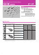
Cylindrical Inductive Proximity Sensor GX-M SERIES
Sensor
size
B
(mm in)
C
(mm in)
M12
12
0.47
12
0.47
M18
18
0.71
18
0.71
M30
30
1.18
30
1.18
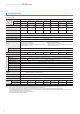
Type
D (mm in) E (mm in)
M8 M12 M18 M30 M8 M12 M18 M30
DC 3-wire
shielded type
18
0.71
24
0.94
60
2.36
120
4.72
3
0.12
4
0.16
10
0.39
20
0.77
DC 3-wire
non-shielded type
-
84
3.30
144
5.67
264
10.39
-
48
1.89
72
2.83
120
4.72
DC 2-wire
standard type
18
0.71
24
0.94
60
2.36
120
4.72
3
0.12
4
0.16
10
0.39
20
0.77
DC 2-wire long
range type
30
1.18
50
1.97
100
3.93
180
7.09
5
0.20
8
0.32
16
0.63
30
1.18
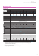
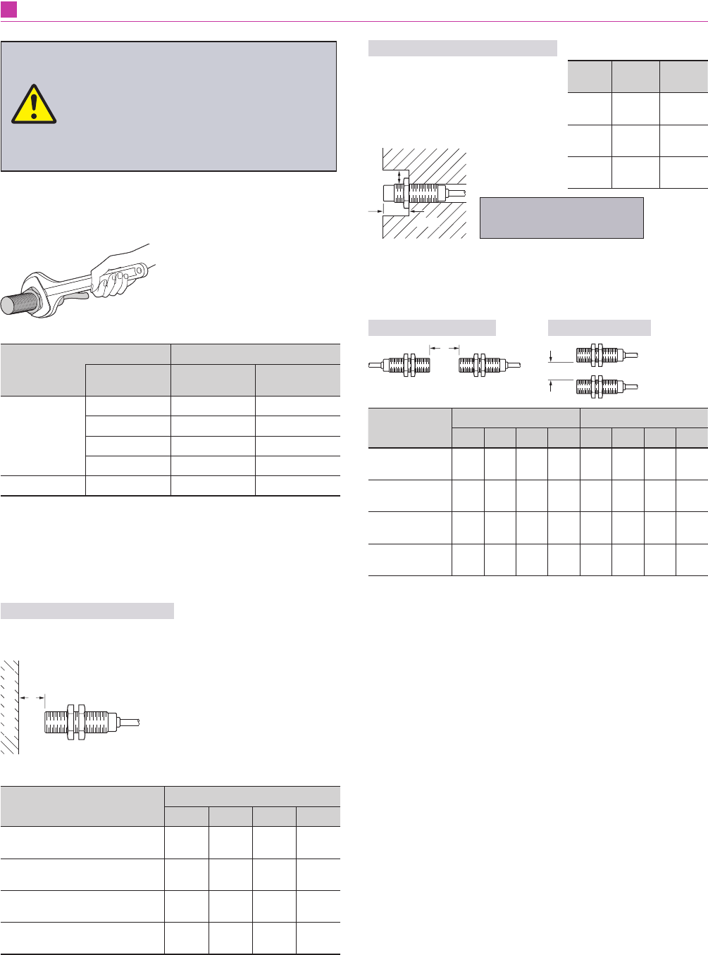
Type
A (mm in)
M8 M12 M18 M30
DC 3-wire shielded type
3
0.12
4
0.16
10
0.39
20
0.79
DC 3-wire non-shielded type -
21
0.83
36
1.42
66
2.60
DC 2-wire standard type
4.5
0.18
6
0.23
15
0.59
30
1.18
DC 2-wire long range type
8
0.32
12
0.47
25
0.98
45
1.77
Model No.
Tightening torque
Sensor size Sensor
Connector
(Note)
GX-M□
M8 5 N·m 2 N·m
M12 6 N·m 2 N·m
M18 15 N·m 2 N·m
M30 40 N·m 2 N·m
GX-M(L)8□-U-J
M8 5 N·m 1.5 N·m
Note: Connector is equipped with -Z type or -J type.
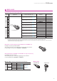
Distance from surrounding metal
•
As metal around the sensor may affect the sensing
performance, pay attention to the following points.
Inuence of surrounding metal
•
The surrounding metal will affect the sensing performance.
Keep the minimum distance specied in the table below.
$
%DFNJURXQGPHWDO
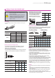
Embedding of the sensor in metal
•
Sensing range may decrease if the
sensor is completely embedded
in metal. Especially for the non-
shielded type, keep the minimum
distance specied in the right table.
&
0HWDO
%
Note: With the non-shielded type, the sensing
range may vary depending on the
position of the nuts.
Mutual interference
•
When two or more sensors are installed in parallel or face
to face, keep the minimum separation distance specied
below to avoid mutual interference.
Face to face mounting
'
Parallel mounting
(
• Never use this product as a sensing device for
personnel protection.
• In case of using sensing devices for personnel
protection, use products which meet laws and
standards, such as OSHA, ANSI or IEC etc.,
for personnel protection applicable in each
region or country.
12