
Datasheet
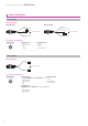
(Brown) +V
+
–
(Blue) 0 V
(Black) Output
Load
12 to 24V DC ±10 %
(Brown) +V
+
–
(Blue) 0 V
(Black) Output
Load
12 to 24V DC ±10 %
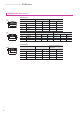
(Brown) +V
+
–
(Blue) 0 V
Load
Load
12 to 24V DC ±10 %
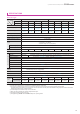
Wiring diagram
Wiring diagram
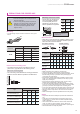
Connector pin position
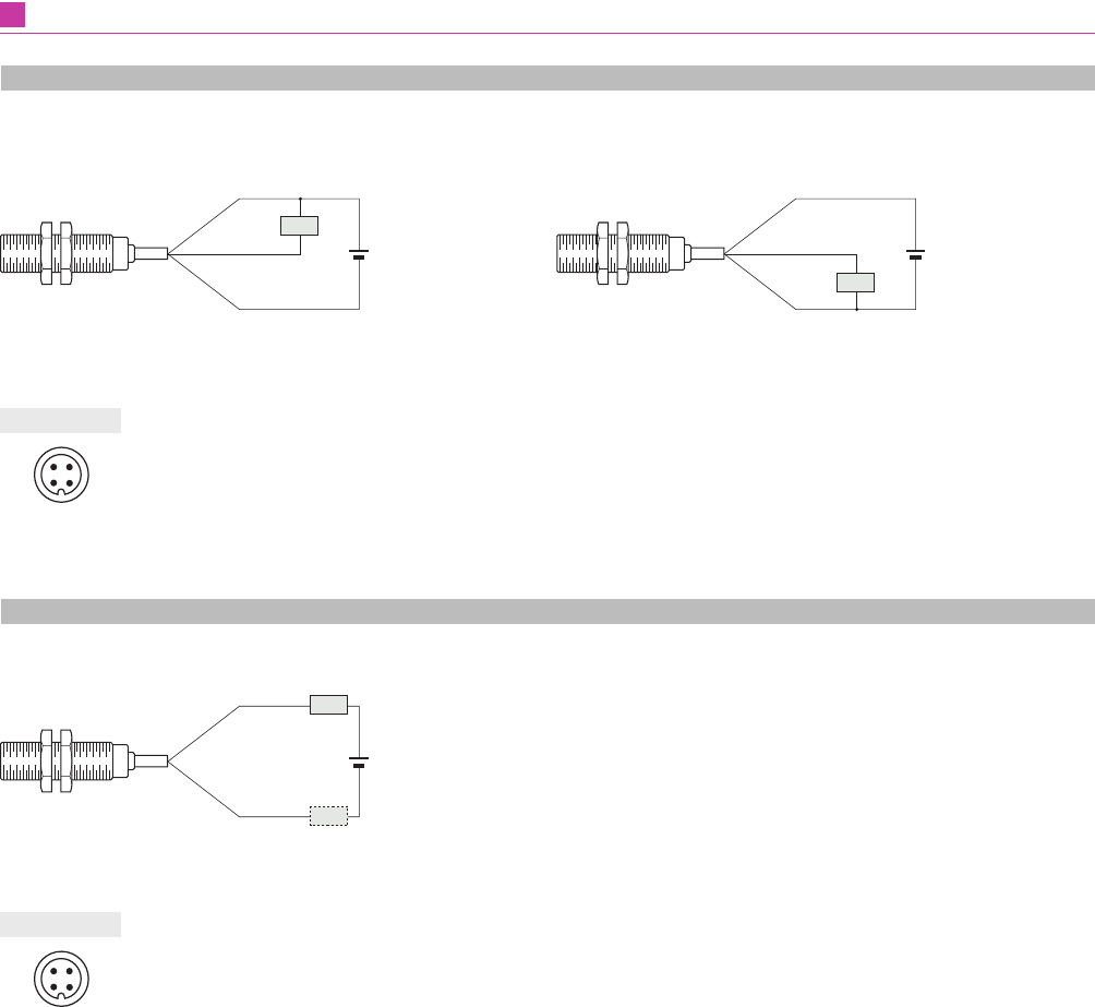
Connector pin position
NPN output type PNP output type
12
43
M12 connector
12
43
M12 connector
• Normally Open
1 : +V
2 : Not connected
3 : 0 V
4 : Output
• Normally Open
(except for GX-M8□-U-J and GX-ML8□-U-J)
1 : Not connected
2 : Not connected
3 : +V
4 : 0 V
• Normally Open
(GX-M8□-U-J and GX-ML8□-U-J only, On sale soon)
1 : +V
2 : Not connected
3 : Not connected
4 : 0 V
• Normally Closed
1 : +V
2 : Output
3 : 0 V
4 : Not connected
• Normally Closed
1 : +V
2 : 0 V
3 : Not connected
4 : Not connected
WIRING DIAGRAMS
DC 3-wire type
DC 2-wire type
Cylindrical Inductive Proximity Sensor GX-M SERIES
11