
Datasheet


FIBER
SENSORS
LASER
SENSORS
PHOTO-
ELECTRIC
SENSORS
MICRO
PHOTO-
ELECTRIC
SENSORS
AREA
SENSORS
SAFETY
COMPONENTS
PRESSURE
SENSORS
INDUCTIVE
PROXIMITY
SENSORS
PARTICULAR
USE
SENSORS
SENSOR
OPTIONS
WIRE-
SAVING
SYSTEMS
MEASURE-
MENT
SENSORS
STATIC
CONTROL
DEVICES
LASER
MARKERS
INDUCTIVE
PROXIMITY
SENSORS
Selection
Guide
Amplifier
Built-in
GXL
GX-F/H
GL
GX-U / GX-FU /
GX-N
GX
GA-311 / GH
Other
Products
Amplifier-
separated
GX-F/H
Amplier
Built-in
Rectangular-shaped Inductive Proximity Sensor GX-F/H SERIES
654
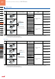
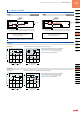
I/O CIRCUIT DIAGRAMS
GX-□
NPN output type
D
Tr
ZD
100 mA max.
Color code
Users’ circuitInternal circuit
(Brown) +V
(Black) Output
(Note)
(Blue) 0 V
12 to 24 V DC
%
+10
–15
Load
Sensor circuit
+
–
D
Tr
ZD1
ZD2
%
+10
–15
Users’ circuitInternal circuit
Color code
100 mA max.
Sensor circuit
Load
(Brown) +V
(Black) Output
(Note)
(Blue) 0 V
+
–
12 to 24 V DC
GX-□-P
PNP output type
Note: The output does not incorporate a short-circuit protection circuit.
Do not connect it directly to a power supply or a capacitive load.
Note: The output does not incorporate a short-circuit protection circuit.
Do not connect it directly to a power supply or a capacitive load.
Symbols … D : Reverse supply polarity protection diode
Z
D1,
Z
D2
: Surge absorption zener diode
Tr : NPN output transistor
Symbols … D : Reverse supply polarity protection diode
Z
D
: Surge absorption zener diode
Tr : PNP output transistor
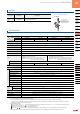
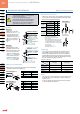
SENSING CHARACTERISTICS (TYPICAL)
GX-8 type
As the sensing object size becomes smaller than
the standard size (iron sheet 15 × 15 × t 1 mm
0.591 × 0.591 × t 0.039 in), the sensing range
shortens as shown in the left gures.
Sensing eld Correlation between sensing object size and sensing range
L
L
ℓ
ℓ
4
0.157
2
0.079
0 2
0.079
4
0.157
Operating point ℓ (mm in)
Standard sensing object
Iron sheet 15 × 15 × t 1 mm
0.591 × 0.591 × t 0.039 in
Standard sensing object
Iron sheet 15 × 15 × t 1 mm
0.591 × 0.591 × t 0.039 in
Top sensing
Front sensing
Center RightLeft
0
1
0.039
2
0.079
4
0.157
3
0.118
Setting distance L (mm in)
L
L
Front sensing
Sensing object
a
×
a mm a
×
a in
t 1 mm
t 0.039 in
t 1 mm
t 0.039 in
Sensing object
a
×
a mm a
×
a in
Top sensing
1
0.039
2
0.079
4
0.157
3
0.118
Sensing range L (mm in)
Sensing object side
length a (mm in)
5
0.197
10
0.394
15
0.591
20
0.787
0
Iron
Stainless steel
(
SUS304
)
Brass
Aluminum
GX-12 type
As the sensing object size becomes smaller than
the standard size (iron sheet 20 × 20 × t 1 mm
0.787 × 0.787 × t 0.039 in), the sensing range
shortens as shown in the left gure.
Sensing eld Correlation between sensing object size and sensing range
10
0.394
5
0.197
0 5
0.197
10
0.394
Operating point ℓ (mm in)
ℓ
ℓ
Center RightLeft
L
L
Standard sensing object
Iron sheet 20 × 20 × t 1 mm
0.
787
× 0.
787
× t 0.039 in
Standard sensing object
Iron sheet 20 × 20 × t 1 mm
0.787 × 0.787 × t 0.039 in
Top sensing
Front sensing
0
2
0.079
4
0.157
8
0.315
6
0.236
Setting distance L (mm in)
Sensing object side
length a (mm in)
Sensing range L (mm in)
L
L
10
0.394
20
0.787
30
1.181
40
1.575
0
2
0.079
4
0.157
8
0.315
6
0.236
t 1 mm
t 0.039 in
Top sensing
t 1 mm
t 0.039 in
Iron
Stainless steel
(
SUS304
)
Brass
Aluminum
Front sensing
Sensing object a
×
a mm a
×
a in
Sensing
object
a
×
a mm
a
×
a in