
Owner's Manual

-
14
-
EN EN
EN EN
Rundown error detecting func-
tion
• The rundown error detecting function causes
a red indicator to flash if work ends more
quickly than a set time, for example due
to retightening of a previously tightened
fastener or binding of the screw’s thread.
1. Set the tool to setting configuration mode.
(See page 11.)
2. Press the B button twice.
• The rundown error detecting function
setting value will be displayed.
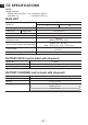
3. Press the
and buttons to change the
time as desired.
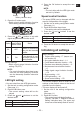
Operation Display Seconds
30 3 seconds
1 0.1 seconds
0 OFF
4. Press the OK button to accept the new
setting.
• When the cross thread reduction func
-
tion is ON, the set time will be counted
after the tool operates in reverse for
approximately 360°.
Maintenance interval alarm
function
•
The maintenance interval alarm function
locks the tool so that it can no longer be
operated once a set number of tightening
operations has been performed. This function
is convenient when regularly inspecting tool
performance, for example.
1. Set the tool to setting configuration mode.
(See page 11.)
2. Press the C button twice.
• The setting value will be displayed.
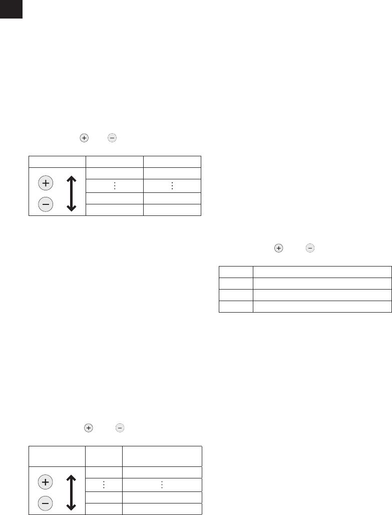
3. Press the
and buttons to set the
desired value.
Operation Display
Number of tightening
operations
99 990,000
1 10,000
0 OFF
4. Press the OK button to accept the new
setting.
NOTE:
• When the remaining number of tighten
-
ing operations is 10,000 or less, the
display will alternate between “Setting”
and “1.” When the remaining number
of tightening operations reaches 0, the
value “0” will flash on the display.
To delay the inspection while retaining
the current tightening operation count
value, select a new setting value that is
greater than the current setting value.
To reset the count to 0, initialize the tool
(see page 15).
• The maximum tightening operation
count value is 990,000. Operations in
excess of 990,000 will not be counted.
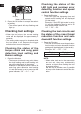
Buzzer setting
• You can select from three buzzer modes.
1. Set the tool to setting configuration mode.
(See page 11.)
2. Press the A button once.
• The current setting value will be dis
-
played.
3. Press the
and buttons to set the
desired value.
Display Function
b0 No buzzer
b1
Buzzer accompanying green indicator
b2 Buzzer accompanying red indicator
4. Press the OK button to accept the new
setting.
NOTE:
• The tool ships with the buzzer mode set
to b0 by default.
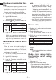
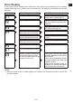
Radio signal range limita-
tion function on/off setting
(EYFPA1JR)
1. Set the tool to configuration mode.
(See page 11.)
2. Press the C button three times.
• The control panel will begin flashing.
Display: The letter “F” ashes on and off.
Battery indication lamp: The upper and
lower bars of the battery ash on and off.