
Owner's Manual
-
14
-
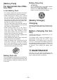
NOTE:
• When other tools are in the area which
are not set, they may accidentally
receive a signal when setting the tool
by remote control.
Set the tool in another room if possible
or keep a fair distance to avoid this situ-
ation.
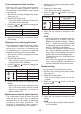
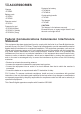
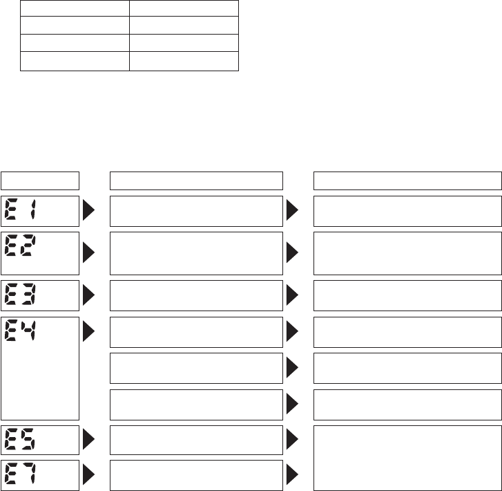
Error Display
In the event of a tool or battery pack malfunction, the control panel will display an error message.
Please check the tool or battery pack as described in the following chart before having them
serviced.
Display Likely cause Corrective action
Setting error Re-initialize the tool using the
remote control. (See page 13.)
The battery pack is too hot. Stop work and allow the battery
pack to cool before resuming use
of the tool.
The tool is too hot to operate. Stop work and allow the tool to
cool before resuming use.
The contacts that connect the
battery pack and tool are dirty.
Remove any dirt.
The battery pack has not been
properly inserted into the tool.
Insert the battery pack rmly into
the tool.
The pins on either the tool or
battery pack have worn down.
Replace the battery pack.
Motor failure, etc. Stop using the tool immediately.
Tool circuit malfunction, failure,
etc.
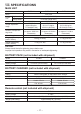
Checking the tool circuits and the
status of the cross thread reduc-
tion function and auto downshift
function settings
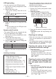
1. Press the D button.
• The tool circuits and cross thread reduc
-
tion function and auto downshift function
settings will be displayed (in that order).
Example: “H3” → “R1” → “10”
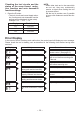
Display Tool circuit
H1 EYFGA1
H2 EYFGA2
H3 EYFGA3