
Datasheet
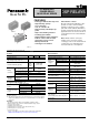


DSP
6
ds_61104_0000_en_dsp: 151106D
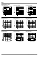
DIMENSIONS
mm inch
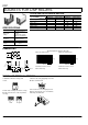
FIXING AND REMOVAL METHOD
SOCKETS FOR DSP RELAYS
SPECIFICATIONS
Item Specifications
Breakdown
voltage
3,000 Vrms between
terminals
(Except for the portion
between coil terminals)
Insulation
resistance
1,000 MΩ between
terminals at 500 V
Heat resistance 150°C for 1 hour
Max. continuous
current
1a: 8 A
2a: 5 A
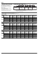
TYPES AND APPLICABLE RELAYS
Type No.
Applicable relays
For DSP1a For DSP1a, DSP1, DSP2a
DSP1a-PS DSP1a-PSL2 DSP2a-PS DSP2a-PSL2
DSP1a relays OK OK OK OK
DSP1a-L2 relays OK OK
DSP1 relays OK OK
DSP1-L2 relays OK
DSP2a relays OK OK
DSP2a-L2 relays OK
5.7–0.3
.224–.012
17–0.6
.669–.024
11–0.6
.433–.024
23–0.6
.906–.024
0.3–0.1
.012–.004
7.62–0.3
.300–.012
10.16–0.3
.400–.012
0.8–0.1
.031–.004
0.65–0.1
.026–.004
7.62–0.3
.300–.012
2.54–0.3
.100–.012
3.7
.146
2.61
.103
PC board pattern (Copper-side view)
DSP1a-PS, DSP1a-PSL2
Terminal No.2 and 15 are for
DSP1a-PSL2 only.
DSP2a-PS, DSP2a-PSL2
Terminal No.2 and 15 are for
DSP2a-PSL2 only.
12
15 16
58
2.54
.100
2.54
.100
1.2 dia.
047 dia.
12
15 16
58
129
2.54
.100
2.54
.100
1.2 dia.
047 dia.
1. Match the direction of relay and
socket.
2. Both ends of relays are fixed so surely
that the socket hooks on the top surface
of relays.
3. Remove the relay, applying force in the
direction shown below.
4. In case there is not enough space for
finger to pick relay up, use screw drivers
in the way shown below.
Good No good