
Datasheet


DSP
4
ds_61104_0000_en_dsp: 151106D
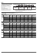
REFERENCE DATA
1. Max. switching capacity 2.-(1) Life curve (1a1b type) 2.-(2) Life curve (1a1b type)
10
0.1
100 1000
Contact voltage, V
Contact current, V
1
10
DC resistive
load (1a)
DC resistive load
(1a1b,2a)
AC resistive
load (1a)
AC resistive
load
(1a1b,2a)
100
10
012 43765
Switching capacity, A
No. of operations, ×10
4
265 V-130 V AC cos
ϕ
= 1
265 V-130 V AC
cos
ϕ
= 0.4
100
50
10
0.5 1 105
Switching capacity, A
No. of operations, ×10
4
30 V DC L/R = 7 ms
30 V DC resistive
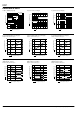
3.-(1) Coil temperature rise (1a type)
Sample: DSP1a-DC12V, 5 pcs.
3.-(2) Coil temperature rise (1a1b type)
Sample: DSP1-DC12V, 5 pcs.
3.-(3) Coil temperature rise (2a type)
Sample: DSP2a-DC12V, 5 pcs.
50
60
40
10
20
30
0
80 100 120
8A
0A
Coil applied voltage, %V
Coil temperature rise, °C
50
60
40
10
20
30
0
80 100 120
5A
0A
Coil applied voltage, %V
Coil temperature rise, °C
50
60
40
10
20
30
0
80 100 120
5A
0A
Coil applied voltage, %V
Coil temperature rise, °C
4.-(1) Operate & release time
(without diode, 1a type)
Sample: DSP1a-DC12V, 5 pcs.
4.-(2) Operate & release time
(without diode, 1a1b type)
Sample: DSP1-DC12V, 5 pcs.
4.-(3) Operate & release time
(without diode, 2a type)
Sample: DSP2a-DC12V, 5 pcs.)
80 100 120
4
3
2
1
0
5
6
7
Max.
x
Max.
Min.
Coil applied voltage, %V
Operate & release time, ms
x
Min.
Operate time
Release time
80 100 110
0
1
2
3
4
5
6
7
8
9
Max.
Min.
x
x
Max.
Min.
Coil applied voltage, %V
Operate & release time, ms
Operate time
Release time
80 100 120
0
1
2
3
4
5
6
7
8
9
Max.
Min.
x
x
Max.
Min.
Coil applied voltage, %V
Operate & release time, ms
Operate time
Release time