
User guide


Connections
Notes on connections
• Read the instruction manual for each system component carefully before
connecting it.
• Turn off the power supply for all components before making any
connections.
• If the cables necessary for connecting a component to the system are not
included with the component or available as an option, you may need to
fashion a cable to suit the component concerned.
• If there is a lot of jitter in the video signal which is input from the video
source, the picture on the screen may flicker, in such cases, it will be
necessary to connect a TBC (time base corrector).
• The projector has built-in speakers. However, you will need to connect a
separate audio system to the AUDIO OUT jack if your needs specify high
sound volumes. No sound will come out of the projector’s built-in speakers
while the AUDIO OUT jack is being used.
• It may not be possible to connect some types of computer. Refer to the list
of compatible signals on page 50.
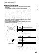
• The pin layout and signal names for the S-VIDEO IN connector are shown
below.
c
CO
(0
Q.
0)
External view
Pin No. Signal
0
Ground (Luminance signal)
CD
Ground (Color signal)
(D
Luminance signal
©
Color signal
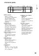
• The pin layout and signal names for the RGBA^PbPr (RGB1 1N/RGB2 IN)
connector are shown below.
CD-
C O O 0 o \
(
P O O 0 c
I,-<3)
External view
Pin No.
Signal
©
R/Pr
(D
G/GSYNCA'
CD
B/Pb
SDA
HD/SYNC
©
VD
SCL
Pin CD is spare.
Pins CjHD. ® and ® are for ground.
Pins ® and ® functions are only valid when
supported by the computer
17