
user manual
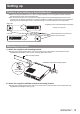

Connections
18 - ENGLISH
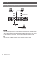
Before connecting
z
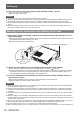
Before connecting, carefully read the operating instructions of the devices to be connected.
z
Turn off the power of all devices before connecting cables.
z
Connect the cables by paying enough attention to the following points. If not, troubles may be led.
• Before start connecting a cable to the interface box or to a device connected to the interface box, touch a
metal to release the charge from the operator’s body.
• Do not use unnecessarily long cables when connecting the interface box and the projector. Longer the cable
is, easier to be inuenced by a noise. If the cable is used in a wrapped condition, it becomes an antenna,
which more easily gets inuenced by a noise.
• When connecting the cable, insert to the connecting terminals of the interface box perpendicularly,
connecting to GND rst.
z
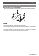
If connecting cables necessary for the system connection are not supplied with the devices as accessories or
not available as an option, prepare cables that are compatible to the connecting devices.
z
Video signals containing too much jitter may cause the images on the screen to randomly wobble or wafture. In
this case, a time base corrector (TBC) must be connected.
z
The interface box accepts video signals, S-video signals, analog RGB signals (synchronous signals are TTL
level), and digital signals.
z
Some computer models are not compatible with the interface box.
z
Refer to “List of compatible signals” (
page 48) for the input image signals that can be used for the interface
box.
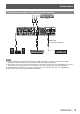
■
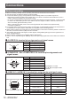
<S-VIDEO IN> terminal pin assignments and signal names
Outside view Pin No. Signal name
(1) (2)
(3) (4)
(1)
GND (luminance signal)
(2) GND (color signal)
(3) Luminance signal
(4) Color signal
■
<COMPUTER 1 IN>/<COMPUTER 2 IN> terminal pin assignments and
signal names
Outside view Pin No. Signal name
(4) and (9) are not used.
(5) - (8), (10), and (11) are GND
terminals.
(10) (6)
(11)(15)
(1)(5)
(1) R/P
R
(2) G/G, SYNC/Y
(3) B/P
B
(12) DDC data
(13) HD/SYNC
(14) VD
(15) DDC clock
■
<HDMI IN 1>/<HDMI IN 2> terminal pin assignments and signal names
Outside view
Pin No. Signal name Pin No. Signal name
(1) T.M.D.S data 2 + (11) T.M.D.S clock shield
(2) T.M.D.S data 2 shield (12) T.M.D.S clock
-
Odd-numbered pins (1) to (19) (3) T.M.D.S data 2
-
(13) CEC
(1)(19)
(2)(18)
(4) T.M.D.S data 1 + (14) —
(5) T.M.D.S data 1 shield (15) SCL
(6) T.M.D.S data 1
-
(16) SDA
(7) T.M.D.S data 0 + (17)
DDC/CEC
GND
Even-numbered pins (2) to (18) (8) T.M.D.S data 0 shield (18) +5 V
(9) T.M.D.S data 0
-
(19) Hot plug detection
(10) T.M.D.S clock +
Connections