Operating Instructions Functional Manual Digital Interface Box Commercial Use Model No. ET-YFB100G Thank you for purchasing this Panasonic product. ■■This manual is intended for products manufactured from May 2013 and beyond. ■■Before operating this product, please read the instructions carefully and save this manual for future use. ■■Before using this product, be sure to read “Read this first!” ( pages 3 to 8).
Trademarks • PJLinkTM is a trademark or pending trademark in Japan, the United States, and other countries and regions. • HDMI, the HDMI Logo, and High-Definition Multimedia Interface are trademarks or registered trademarks of HDMI Licensing LLC in the United States and other countries. • VGA and XGA are trademarks of International Business Machines Corporation. • SVGA is a registered trademark of the Video Electronics Standards Association.
Information Read this first! Read this first! WARNING: THIS APPARATUS MUST BE EARTHED. WARNING: TO REDUCE THE RISK OF FIRE OR ELECTRIC SHOCK, DONOT EXPOSE THIS PRODUCT TO RAIN OR MOISTURE. WARNING: 1. Remove the plug from the mains socket when this unit is not in use for a prolonged period of time. 2. To prevent electric shock, do not remove cover. No user serviceable parts inside. Refer servicing to qualified service personnel. 3. Do not remove the earthing pin on the mains plug.
Read this first! FCC NOTICE (USA) Declaration of Conformity Model Number: ET-YFB100G Trade Name: Panasonic Responsible Party: Panasonic Corporation of North America Address: One Panasonic Way, Secaucus, NJ 07094 Telephone number: (877)803-8492 E-mail: projectorsupport@us.panasonic.com This device complies with Part 15 of the FCC Rules.
Read this first! IMPORTANT: THE MOULDED PLUG (U.K. only) FOR YOUR SAFETY, PLEASE READ THE FOLLOWING TEXT CAREFULLY. This appliance is supplied with a moulded three pin mains plug for your safety and convenience. A 13 amp fuse is fitted in this plug. Should the fuse need to be replaced, please ensure that the replacement fuse has a rating of 13 amps and that it is approved by ASTA or BSI to BS1362. or the BSI mark on the body of the fuse.
Read this first! WARNING: POWER The wall outlet or the circuit breaker shall be installed near the equipment and shall be easily accessible when problems occur. If the following problems occur, cut off the power supply immediately. Continued use of the device in these conditions will result in fire or electric shock. zz If foreign objects or water get inside the device, cut off the power supply. zz If the device is dropped and the AC adaptor is damaged, cut off the power supply.
Read this first! WARNING: ON USE/INSTALLATION Do not place the device on soft materials such as carpets or sponge mats. Doing so will cause the device to overheat, which can cause burns, fire or damage to the device. Do not set up the device in humid or dusty places or in places where the device may come into contact with oily smoke or steam, ex. a bathroom. Using the device under such conditions will result in fire or electrical shock. Do not block the exhaust ports or cover them with cloth, paper, etc.
Read this first! CAUTION: POWER When disconnecting the power cord, be sure to hold the power plug and power connector. If the power cord itself is pulled, the lead will become damaged, and fire, short-circuits or serious electric shocks will result. When not using the device for an extended period of time, disconnect the power plug from the wall outlet. Failure to do so may result in fire or electric shock. Disconnect the power plug from the wall outlet before carrying out any cleaning of the device.
Features of this product Easy setup and improved serviceability ▶▶Outputs the image, sound, ethernet, and serial control signals digitally by using one cable with CAT5e or higher grade to the projector*1 at a distance up to 100 m (328'11"). *1: Supported only when the interface box is connected to a DIGITAL LINK compatible projector. ▶▶The light-weight and compact-size body is achieved that can be easily attached to the rack or the underside of the tabletop of the meeting desk.
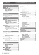
Contents Be sure to read “Read this first!”. ( pages 3 to 8) Important Information Read this first!............................................. 3 Precautions for use....................................11 Cautions when transporting.............................. 11 Cautions when installing................................... 11 Disposal........................................................... 11 Accessories..................................................... 12 Preparation About your interface box...
Precautions for use Precautions for use Cautions when transporting zzWhen transporting the interface box, avoid excessive vibration and impacts. Doing so may damage the internal parts and result in malfunctions. Cautions when installing ■■Do not set up the interface box outdoors. The interface box is designed for indoor use only. ■■Do not set up the interface box in the following locations.
Precautions for use Accessories Make sure that the following accessories are provided with your interface box. Numbers enclosed in < > show the number of accessories. AC adaptor <1> (CF-AA6373AM1) Power cord <1> (For USA) (K2CG3YY00152) Power cord <1> (For Europe) (K2CM3YY00034) Power cord <1> (For U.K.
About your interface box About your interface box Main body ■■Front and lateral sides ■■Rear and bottom sides (5) (4) (6) (4) (3) (2) (7) (3) (1) (2) (1) Control panel ( page 13) (5) Mounting bracket screw hole for securing AC adaptor ( page 23) (2) Rack mount screw hole Screw holes for the fixing bracket that is used to mount the interface box to the rack.
About your interface box ■■Connecting terminals (1) (6) (2) (7) (8) (3) (9) (1) terminal Terminal to remotely operate the interface box via the external control circuit. (2) terminal The RS-232C compatible terminal used for the external control. The projector connected by the DIGITAL LINK can be externally controlled. Controlling the interface box is disabled. (3)
Setting up Setting up Cautions when setting up the interface box zzWhen mounting the interface box to a rack or a table underside, use the supplied rack/table underside mounting bracket or the rack mounting bracket. zzUse a torque screwdriver or torque wrench to tighten bolts to their specified tightening torques. Do not use tools such as electric screwdrivers or impact screwdrivers.
Setting up 3) Fix to the rack by using the commercially available screws*1 (4 pcs). *1: Use M5 or M6 screws for EIA standard rack. zzSecurely tighten the screws. Attention zzDuring attachment, be careful that the interface box does not slip. zzBe sure to fix the cables connected to the connecting terminals and the supplied AC adaptor nearby such as the supports of the rack to avoid the cable and AC adaptor weights directly applied to the interface box.
Setting up Mounting on the desk or the shelf Mount the supplied set legs to the interface box. zzMount the legs to the set leg screw holes at the bottom side of the interface box with the supplied set leg screws (4 pcs). Securely tighten the screws. 6HW OHJV Attention zzWhen mounting the interface box on a table or on a shelf, always use the set legs. When buttons on the control panel are pressed, the interface box may slip and cause a flaw on the table or the shelf.
Connections Connections Before connecting zzBefore connecting, carefully read the operating instructions of the devices to be connected. zzTurn off the power of all devices before connecting cables. zzConnect the cables by paying enough attention to the following points. If not, troubles may be led. • Before start connecting a cable to the interface box or to a device connected to the interface box, touch a metal to release the charge from the operator’s body.
Connections Connecting example: Video and audio devices 9&5 +'0, FDEOH FRPPHUFLDOO\ DYDLODEOH $XGLR HTXLSPHQW '9' SOD\HU %OX UD\ GLVF SOD\HU Note zzUse an HDMI High Speed cable that conforms to HDMI standards. If a cable not conforming the HDMI standard is used, the image may be interrupted or may not be displayed properly. zzThe interface box can connect to an external device, which has a DVI terminal, with the HDMI/DVI conversion cable.
Connections Connecting example: Computers Computer Control computer Computer cable (commercially available) Hub Control computer Attention zzWhen connecting the interface box to a computer or an external device, use the power cord supplied with each device and commercially available shielded cables. zzThe positions of the and terminals are close each other. Therefore, when connecting cables to both terminals, removing the cable connected to the terminal may be difficult.
Connections Connecting to the DIGITAL LINK compatible device ■■Connections When connecting to the DIGITAL LINK compatible projector When connecting to the projector that is not DIGITAL LINK compatible The twisted-pair-cable receiver of other manufacturer DIGITAL LINK compatible projector HDMI cable (commercially available) * Names of the DIGITAL LINK terminals may be different for each manufacturer.
Connections Note zzThe maximum transferable distance is 100 m (328'11"). When the distance is longer than this maximum distance, the image or the sound may be interrupted, or erroneous performance occurs in LAN. If the interface box is used with the distance longer than the specified maximum transferable distance, the operation will be out of our warranty. zzWhen Panasonic projector, which is not DIGITAL LINK compatible, is connected, the recommended twistedpaircable receiver is required.
Switching on/off the Switching interface box on/off the interface box Connecting the AC adaptor Confirm that the button of the interface box is off, and then connect the power cord and the AC adaptor. For details of the AC adaptor and the power cord handling, refer to “Read this first!”( pages 3 to 8). ■■To attach the power cord 1) Fully and securely insert the power cord to the AC adaptor. Then, securely insert the AC adaptor plug to the terminal at the connecting terminals.
Switching on/off the interface box ■■To remove the power cord 1) Confirm that the button of the interface box is off, and remove from the power outlet by holding the power plug. 2) Remove the mounting bracket for securing AC adaptor. (i) Remove the mounting bracket screw for securing AC adaptor. (ii) Remove the mounting bracket for securing AC adaptor. (i) (ii) 3) Hold the AC adaptor plug and remove the AC adaptor from the terminal of the interface box.
Checking the image Checking the image Confirm the connections of the external device ( page 18) and the AC adaptor ( page 23) and then turn on the power ( page 24). Select the projecting image, and confirm that the selected image is projected from the projector. Select the input signal Select an input signal. 1) Turn on the external device. zzTurn on the external devices such as a projector and a Blu-ray disc player.
Remote control operation Remote control operation The interface box can be operated by the remote control of the connected projector (only DIGITAL LINK compatible models). Some remote controls do not have some buttons and perform differently. zzIf the remote control signal receiver of the connected projector directly receives strong light, such as fluorescent light, the remote control may not operate properly. Use it in a place distant from the light source.
On-screen menu navigation On-screen menu navigation The on-screen menu (Menu) is used to perform various settings and adjustments of the interface box. Navigating through the menu ■■Operating procedure button 1) Press the
On-screen menu navigation Note zzThe remote control may not have the default button, depending on the DIGITAL LINK compatible projector model connected to the interface box. zzTo restore all settings to the factory default settings simultaneously, refer to [OPTION] on the menu → [INITIALIZE ALL] ( page 40). zzThe mark above the bar scale in the individual adjustment screen indicates the factory default setting. The position of this mark varies depending on the selected input signals.
[INPUT SELECT] menu [INPUT SELECT] menu Select [INPUT SELECT] from the main menu, and display the sub-menu. Refer to “Navigating through the menu” ( page 27) for the operation of the menu screen. Switching the input An input terminal for the image can be selected. zzPress ▲▼ to select an input terminal and press the button to set. [HDMI 1] Switches to HDMI 1 input. [HDMI 2] Switches to HDMI 2 input. [COMPUTER 1] Switches to COMPUTER 1 input. [COMPUTER 2] Switches to COMPUTER 2 input.
[PICTURE] [PICTURE] menumenu Select [PICTURE] from the main menu, and select the item from the sub-menu. Refer to “Navigating through the menu” ( page 27) for the operation of the menu screen. [SYSTEM SELECTOR] The interface box will automatically detect the input signal, but you can set the system method manually when an unstable signal is input. Set the system method matching the input signal. 1) Press ▲▼ to select [SYSTEM SELECTOR]. 2) Press ◀▶ or the button.
[PICTURE] menu [DIGITAL CINEMA REALITY] The vertical resolution can be improved when the function is used in the 2-2 and 2-3 pull down. Supported only when certain signals are input. 525i (480i), 625i (576i), 1125 (1080)/60i, 1125 (1080)/50i, S-video signal, and video signal 1) Press ▲▼ to select [DIGITAL CINEMA REALITY]. 2) Press ◀▶ or the button. zzThe [DIGITAL CINEMA REALITY] individual adjustment screen is displayed. 3) Press ◀▶ to switch [DIGITAL CINEMA REALITY].
[POSITION] [POSITION] menu menu Select [POSITION] from the main menu, and select the item from the sub-menu. Refer to “Navigating through the menu” ( page 27) for the operation of the menu screen. [CLOCK PHASE] You can adjust to achieve an optimal image when there is a flickering image or smeared outlines. 1) Press ▲▼ to select [CLOCK PHASE]. 2) Press ◀▶ or the button. zzThe [CLOCK PHASE] individual adjustment screen is displayed.
[POSITION] menu [ASPECT] Aspect mode Input signal You can switch the aspect ratio of the image. 1) Press ▲▼ to select [ASPECT]. 2) Press ◀▶ or the button. zzThe [ASPECT] individual adjustment screen is displayed. 3) Press ◀▶ to switch the setting. zzThe aspect ratio changes as follows each time the button is pressed.
[POSITION] menu Aspect mode Screen Aspect mode Input signal Input signal [FULL] Outputs the image by using whole effective area of the image signals output from the terminal. Projection screen Screen [V FIT] Outputs the image with the aspect ratio fixed and by using whole effective area in the vertical direction of the image signals output from the terminal.
[LANGUAGE] menu [LANGUAGE] menu Select [LANGUAGE] from the main menu, and display the sub-menu. Refer to “Navigating through the menu” ( page 27) for the operation of the menu screen. Changing the display language You can select the language of the on-screen display. zzPress ▲▼ to select a language, and press the button to set.
[OPTION] [OPTION] menumenu Select [OPTION] from the main menu, and select the item from the sub-menu. Refer to “Navigating through the menu” ( page 27) for the operation of the menu screen. [OSD DESIGN] Set the color of the menu screen (OSD). 1) Press ▲▼ to select [OSD DESIGN]. 2) Press ◀▶ to switch [OSD DESIGN]. zzThe setting will change as follows each time you press the button. [TYPE1] [TYPE2] [TYPE1] Displays the background in blue. [TYPE2] Displays the background in black.
[OPTION] menu [SXGA MODE] [NO SIGNAL SLEEP] Sets when the entire image is not displayed while SXGA is input. Set it to [SXGA] normally. 1) Press ▲▼ to select [SXGA MODE]. 2) Press ◀▶ to switch [SXGA MODE]. zzThe setting will change as follows each time you press the button.
[OPTION] menu ■■[AUDIO OUT SELECT] [AUDIO SETTING] The sound output is set. Sets the details of the sound function. 1) Press ▲▼ to select [AUDIO SETTING]. 4) Select [AUDIO OUT SELECT] in step 3). 2) Press the button. 5) Press ◀▶ to switch [AUDIO OUT SELECT]. 3) Press ▲▼ to select an item. [DIGITAL LINK] zzThe [AUDIO SETTING] screen is displayed. ■■[VOLUME] When [AUDIO OUT SELECT] is set to [AUDIO OUT], the volume of the sound output can be adjusted. 4) Select [VOLUME] in step 3).
[OPTION] menu [AUTO SETUP] [OUTPUT RESOLUTION] Sets the auto setup function. Set it to [AUTO] normally. Sets the resolution of the image output from the terminal. 1) Press ▲▼ to select [AUTO SETUP]. 1) Press ▲▼ to select [OUTPUT RESOLUTION]. 2) Press the button. zzThe [AUTO SETUP] screen is displayed. 3) Press ▲▼ to select [AUTO SETUP SETTING]. 4) Press ◀▶ to switch [AUTO SETUP SETTING]. zzThe setting will change as follows each time you press the button.
[OPTION] menu [STATUS] Displays the status of the interface box. 1) Press ▲▼ to select [STATUS]. 2) Press the button. zzThe [STATUS] screen is displayed. [SIGNAL] [NAME] Displays the input signal name. Displays the frequency of the [FREQUENCY] input signal. [SERIAL NUMBER] [INTERFACE BOX] Displays the serial number of the projector. [INITIALIZE ALL] Return various setting values to their factory default settings.
Maintenance Maintenance After a long term usage, exhaust ports at upper and lateral sides of the interface box may be clogged with dust or trash. Clean the exhaust ports periodically. Wipe off dirt and dust on the outer case with a soft, dry cloth. zzWhen removing dirt and dust, do not drop them inside the interface box. zzIf the dirt is persistent, soak the cloth with water and squeeze firmly. Wipe with the wet cloth and finish with a dry cloth.
Troubleshooting Troubleshooting Review the following points. For details, refer to the corresponding pages. Problems Points to be checked zzIs the power plug firmly inserted into the outlet? zzIs the power connector firmly inserted into the AC adaptor? Power does not turn zzIs the AC adaptor plug securely inserted to the main body? on.
Frequently Asked Questions Frequently Asked Questions Check the following. Video is not projected across the entire screen when HDMI signals are input from a computer. Perform the following two steps. zzAdjust the aspect ratio of screens output by a computer to suit projector pixels (aspect ratio). Example: If projector produces images of 1024 dots x 768 dots (4:3), set computer resolution to 800 x 600 (4:3). zzSet [Aspect] to [Full].
Technical information Technical information PJLink protocol The terminal of the interface box conforms with 100Base-T and 10Base-T. Signals are directly transferred to the using projector via DIGITAL LINK. Therefore, when PJLink protocol is used, follow the Operating Instructions of the using projector. The interface box cannot be controlled from this terminal.
Technical information terminal The terminal of the interface box conforms with RS-232C. Signals are directly transferred to the using projector via DIGITAL LINK. For the detailed specifications of the control, see the Operating Instructions of the projector. ■■Connection :KHQ FRQQHFWLQJ WR WKH ',*,7$/ /,1. FRPSDWLEOH SURMHFWRU :KHQ FRQQHFWLQJ WR WKH SURMHFWRU WKDW LV QRW ',*,7$/ /,1.
Technical information ■■Communication conditions Signal level Sync.
Technical information terminal Even when the signal from the remote control cannot reach the projector, the interface box can be remotely controlled (external control) from a control panel installed at a separate place when the terminal of the interface box is used.
Technical information List of compatible signals Image signals that are compatible with the input of the interface box are as shown in the following table. Mode Signal name display Resolution (Dots) Scanning frequency Plug and play compatible Dot clock Frequency Format*1 Horizontal Vertical COMPUTER HDMI (MHz) (kHz) (Hz) 1/2 1/2 NTSC/NTSC4.43/PAL-M/ PAL60 PAL/PAL-N/SECAM 525i (480i) 625i (576i) 525p (480p) — — 15.7 59.9 — V/S ― ― — 480i 576i 480p — 720 x 480i 720 x 576i 720 x 483 15.6 15.
Technical information Scanning frequency Plug and play compatible Dot clock Frequency Format*1 Horizontal Vertical COMPUTER HDMI (MHz) (kHz) (Hz) 1/2 1/2 Mode Signal name display Resolution (Dots) SXGA SXGA60 1 280 x 1 024 64.0 60.0 108.0 R/H SXGA75 1 280 x 1 024 80.0 75.0 135.0 R/H SXGA85 SXGA+60 SXGA+60 1 280 x 1 024 1 400 x 1 050 1 400 x 1 050 91.1 65.2 65.3 85.0 60.0 60.0 157.5 122.6 121.8 WXGA+ UXGA SXGA+75 WXGA+60 UXGA60 1 400 x 1 050 1 440 x 900 1 600 x 1 200 82.2 55.9 75.
Specifications Specifications The following table describes the specifications of the interface box. Model No. ET-YFB100G Power supply DC 16 V (DC input terminal) Power consumption 16 W (when the power is “off”: 0.2 W) (including the supplied AC adaptor) AC adaptor Applicable scanning frequency*1 Input AC 100 - 240 V, 0.8 - 1.5 A, 50 Hz/60 Hz Output DC 16 V 3.75 A For HDMI signals Horizontal: 27.0 kHz to 99.0 kHz, Vertical: 24.0 Hz to 119.8 Hz Dot clock frequency: 25.2 MHz to 162.
Specifications Model No. ET-YFB100G 2 set, high-density D-Sub 15 p (female) / terminal Terminals RGB signals G: 0.7 V [p-p] 75 Ω (SYNC ON GREEN: 1.0 V [p-p] 75 Ω) B,R: 0.7 V [p-p] 75 Ω SYNC/HD/VD TTL, automatic positive/negative polarity compatible YPBPR signals Y: 1.0 V [p-p] including synchronization signal, PBPR: 0.7 V [p-p] 75 Ω
Dimensions Dimensions 8QLWV PP )URQW )URQW ■■When mounting on the rack 250 (9-27/32") Units: mm Front 31.75 (1-1/4") 25 (31/32") 247.2 (9-23/32") 210 (8-9/32") (482.2) (18-31/32") 52 - ENGLISH Front 44 (1-23/32") 465.1 (18-5/16") (8.
Dimensions ■■When mounting to the underside of the tabletop of the desk 8QLWV PP )URQW )URQW ■■When mounting on the desk or the shelf 8QLWV PP )URQW )URQW ENGLISH - 53
Index Index A AC adaptor… ……………………………………… Accessories… ……………………………………… [ASPECT]… …………………………………………
Information on Disposal for Users of Waste Electrical & Electronic Equipment (private households) This symbol on the products and/or accompanying documents means that used electrical and electronic products should not be mixed with general household waste. For proper treatment, recovery and recycling, please take these products to designated collection points, where they will be accepted on a free of charge basis.