
Installation Manual

7
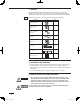
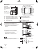
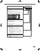
Basic wiring diagram of control wiring
A max.of 64 indoor units and 30 outdoor units can be
connected in 1system.
Up to 10 system controllers can be connected in
1 systems.
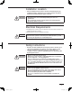
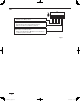
Using Schedule Timer(CZ-ESWC2) with System Controller(CZ-64ESMC1U)•
BASIC DIAGRAM
T10
(YEL)
U1 U2
Inter-unit
control wiring
Schedule
Timer
Communication
wiring(pink + blue)
Power wiring
(white + black)
CZ-ESWC2
Indoor unit
control PCB
Indoor unit
T10
(YEL)
CZ-64ESMC1U
B6
B5 B3 B2 B1B4
System Controller
Indoor unit
control PCB
Electric Wire
supplied with
CZ-64ESMC1U
Indoor unit
U1 U2
It is prohibited to connect the Schedule Timer(CZ-ESWC2) with System Controller(CZ-64ESMC1U) simultaneously.•
Inter-unit
control wiring
Schedule
Timer
Communication
wiring (pink + blue)
Power wiring
(white + black)
CZ-ESWC2
T10
(YEL)
CZ-64ESMC1U
B6 B5 B3 B2 B1B4
System Controller
Indoor unit
control PCB
Indoor unit
U1 U2
Electric Wire
supplied with
CZ-64ESMC1U
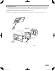
Inter-unit
control wiring
System controller
Indoor
unit1-1
Outdoor
unit-1
Remote
controller
Indoor
unit2-1
Outdoor
unit-2
Remote
controller
Indoor
unit3-1
Outdoor
unit-3
Remote
controller
CZ-64ESMC1U_eng.indd 7CZ-64ESMC1U_eng.indd 7 2011/09/20 19:14:582011/09/20 19:14:58