
Installation Manual

12
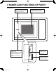
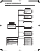
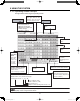
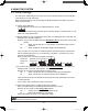
4 NAMES AND FUNCTIONS OF PARTS
Power connector panel
AC100V-240V power
connector panel.
Power switch
Powers the Intelligent Controller
on and off.
OFF ON
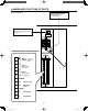
Communications connector panel
1
2
3
4
5
6
7
8
9
10
11
12
ADAPT
(RS-485)
U1
U2
U1
U2
Connect to
communication
adaptor.
DO-COMM
DO 1
DO 2
DI-COMM
DI 1
DI 2
LINK1
Indoor/outdoor
control wire 1
LINK2
Indoor/outdoor
control wire 2
All alarm output
All start input
All operation
output
All stop input
●
Right side panel
CZ-256ESMC1U_改.indb 12CZ-256ESMC1U_改.indb 12 2011/11/11 11:25:012011/11/11 11:25:01