
Brochure

10
Features Chart/Explanation
1
2
3
Terminal
1
UNIT B
2
3
4
UNIT C
5
6
7
UNIT D
8
9
10
11
12
1
2
L1
L2
INDOOR UNIT
UNIT A
(A)
1
2
3
Terminal
INDOOR UNIT
(B)
Terminal
(
2P
)
Terminal
(
12P
)
OUTDOOR UNIT
Disconnect
switch
230/208V
230/208V
230/208V
230/208V
230/208V
230/208V
Grounding line
Grounding line
Field supply
230/208V
230/208V
230/208V
230/208V
1
2
3
Terminal
INDOOR UNIT
(C)
1
2
3
Terminal
INDOOR UNIT
(D)
(Inter-unit)
power line
230/208V
230/208V
Power supply
Single-phase 230/208VAC 60HZ
Grounding line
Grounding
line
Grounding
line
Disconnect switch
Field supply
Disconnect
switch
Field supply
Disconnect switch
Field supply
(A)
(B)
(B)
(B)
(B)
(B)
(B)
(B)
(B)
(C)
(C)
(C)
(C)
*
*
*
*
Benefits
• High Efficiency systems up to 21 SEER
• Inverter Driven variable speed rotary compressor
• Precise compressor speed to match the building needs
• Quiet operation
• Designed to run longer periods at reduced speeds to
improve dehumidification with local codes on wire size
• Quick and easy installation of indoor and outdoor units
• Wired & wireless remote controllers available at option
(Except for some models).
• Single Point Power Supply reduces installation costs
(Comply with local codes on wire size)
• 7 Year compressor warranty and 5 year parts warranty
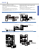
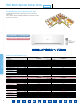
RAC Multi wiring schematic
(example shown is with 4 indoor units)
1
2
3
4
5
6
G
Power
Supply
Ground
Outdoor Unit
115 or 208/230
115 or 208/230
12-15 VDC Signal
1
2
3
G G
Indoor Unit
Disconnect Switch
(Field Supplied)
Disconnect Switch
(Field Supplied)
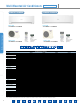
9,000 - 24,000 Btu/h single zone, KS30/36 NKUA, KE30/36NKU
26,000 - 42,000 Btu/h single zone wiring schematic
(Except KS30/36NKUA, KE30/36NKU)
Indoor Unit Outdoor Unit Indoor Unit Outdoor Unit
Indoor Unit
Fig. 25b
Outdoor Unit
For S9/12/18/24/NKUA, S9/12/18/22/NKU-1,
E9/12/18/24NKUA
For CU-2S18NBU-1 / CU-2E18NBU4 indoor units with CU-4KE24NBU, CU-4KE31NBU
U2
L2
U1
L1
L1
L2
U1
U2
2
1
WHT
Remote
Controller
B
Indoor
unit
L1*
L2*
Grounding line
BLK
2
1
Inter-unit power line
208 / 230 V, 60 Hz
, 1-PH
Power supply
208 / 230 V, 60Hz, 1-PH
Grounding line
A
Outdoor unit
INV unit
1
2
G
*Disconnect Switch to be field supplied.
*
*
* These wining diagrams are for reference only. Please refer to installation manual for details.
* Please be sore to follow National / Local code for installation.