
Submittal

Panasonic North America
Air Conditioning Division
1690 Roberts Blvd., NW, Suite 110
Kennesaw, GA 30144
us.panasonic.com/aircon
7/8
1-7/8
5-1/4
Remote control
Remote control holder
2
2-3/8
AUTO
COMFOR T
MO DE
POWER FUL/
QUIET
TE M P
OF F/ O N
TIM ER
SET
CANC EL
ON
OFF
1 2 3
AIR SWING
FAN SPEED
SET CHECK CLOCK RE SET
AC
RC
ECON AVI
FAN
SPE ED
AIR
SWI NG
AUT O
HEAT
COO L
DRY
FAN
/
T
E
M
P
O
F
F
/
O
N
TIM ER
S
ET
CANC EL
O
N
OFF
1
2
3
C
HE
C
K
5/8
10-3/8
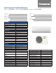
Relative position between the indoor unit and the installation plate <Front View>
Unit: inch
29-29/64
5-1/16
3-3/4
1-11/16
23/71-923/71-9
5-1/16
Right
piping
hole
Left
piping
hole
Installation
plate
Indoor unit
external
dimensions
line
1717-9/32
(8-7/16)
11-7/16
2-13/32
1-49/64
8-7/16
1/32~1/16
1/32~1/16
34-9/32
4-17/32
(1-5/8~2-13/32)
16-1/8
Liquid side
Gas side
4-29/32
2-11/322-11/32
<Side View>
<Side View>
<Top View>
<Front View>
<Bottom View>
<Rear View>
Air intake
direction
Air outlet
direction
Left piping
hole
Right piping
hole
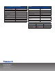
Indoor Dimensions
7/8
1-7/8
5-1/4
Remote control
Remote control holder
2
2-3/8
AUTO
COMFOR T
MO DE
POWER FUL/
QUIET
TE M P
OF F/ O N
TIM ER
SET
CANC EL
ON
OFF
1 2 3
AIR SWING
FAN SPEED
SET CHECK CLOCK RE SET
AC
RC
ECON AVI
FAN
SPE ED
AIR
SWI NG
AUT O
HEAT
COO L
DRY
FAN
/
T
E
M
P
O
F
F
/
O
N
TIM ER
S
ET
CANC EL
O
N
OFF
1
2
3
C
HE
C
K
5/8
10-3/8
Relative position between the indoor unit and the installation plate <Front View>
Unit: inch
29-29/64
5-1/16
3-3/4
1-11/16
23/71-923/71-9
5-1/16
Right
piping
hole
Left
piping
hole
Installation
plate
Indoor unit
external
dimensions
line
1717-9/32
(8-7/16)
11-7/16
2-13/32
1-49/64
8-7/16
1/32~1/16
1/32~1/16
34-9/32
4-17/32
(1-5/8~2-13/32)
16-1/8
Liquid side
Gas side
4-29/32
2-11/322-11/32
<Side View>
<Side View>
<Top View>
<Front View>
<Bottom View>
<Rear View>
Air intake
direction
Air outlet
direction
Left piping
hole
Right piping
hole
7/8
1-7/8
5-1/4
Remote control
Remote control holder
2
2-3/8
AUTO
COMFOR T
MO DE
POWER FUL/
QUIET
TE M P
OF F/ O N
TIM ER
SET
CANC EL
ON
OFF
1 2 3
AIR SWING
FAN SPEED
SET CHECK CLOCK RE SET
AC
RC
ECON AVI
FAN
SPE ED
AIR
SWI NG
AUT O
HEAT
COO L
DRY
FAN
/
T
E
M
P
O
F
F
/
O
N
TIM ER
S
ET
CANC EL
O
N
OFF
1
2
3
C
HE
C
K
5/8
10-3/8
Relative position between the indoor unit and the installation plate <Front View>
Unit: inch
29-29/64
5-1/16
3-3/4
1-11/16
23/71-923/71-9
5-1/16
Right
piping
hole
Left
piping
hole
Installation
plate
Indoor unit
external
dimensions
line
1717-9/32
(8-7/16)
11-7/16
2-13/32
1-49/64
8-7/16
1/32~1/16
1/32~1/16
34-9/32
4-17/32
(1-5/8~2-13/32)
16-1/8
Liquid side
Gas side
4-29/32
2-11/322-11/32
<Side View> <Side View>
<Top View>
<Front View>
<Bottom View>
<Rear View>
Air intake
direction
Air outlet
direction
Left piping
hole
Right piping
hole
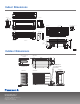
Outdoor Dimensions
<Side View>
<Side View> <Front View>
<Top View>
Unit : inch
30-23/321
2-5/8
1/2
21-9/ 32
(3/4)
(2-3/4) (2-3/8)
11-13/32
1-3/86-1/ 8
3-3/8
22-1/2
(4-1/8)
4-1/8 2-3/8
2-way valve at Liquid side
(High Pressure)
3-way valve at Gas side
(Low Pressure)
Space necessary for
installation
Anchor Bolt Pi tch
12-5/8 x 22-1/2
39-3/8
3-7/8
3-7/8