
Operator's Manual
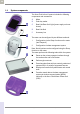
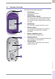
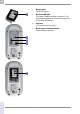
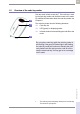
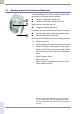
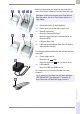
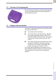
Table Of Contents
- What is new in publication version 7.2?
- 1 Introduction
- 1.1 Before you start
- 1.2 Important safety instructions and additional information
- Important information regarding safety
- Disposal of the system
- Product safety
- General care
- Accessory box
- Meter
- Power off meter
- Automatic power-off
- Shut down meter
- Automatic shutdown
- Battery Pack
- Touchscreen
- Electromagnetic compatibility (EMC)
- Electrostatic discharge (ESD)
- Wireless connectivity
- Radiofrequency radiation exposure information
- Local Area Network: protection from unauthorized access
- Wired network connection
- 1.3 System components
- 1.4 Overview of the meter
- 1.5 Overview of the code key reader
- 1.6 Overview of the Accu-Chek Inform II Base Unit
- 1.7 Overview of the Accu-Chek Inform II Base Unit Hub
- 1.8 Overview of the accessory box
- 1.9 Reagents and consumables
- 1.10 Instructions for initial setup
- 2 Powering Up and Entering an Operator ID
- 3 Patient Glucose Testing
- 3.1 Information regarding blood glucose testing
- 3.2 Performing a patient glucose test
- Overview of test procedure
- Entering or selecting the patient ID
- Entering the patient ID manually
- Selecting the patient ID from a list
- Entering a patient ID with barcode scanner
- Confirming or selecting the test strip lot
- Patient identification information
- Inserting test strips
- Obtaining a blood sample
- Applying a blood sample
- Results screen
- Adding comments
- Add barcode content to a result
- Additional Patient Test
- 4 Glucose Control Testing
- 5 Review Results
- 6 Storing Test Strip, Control Solution, and Linearity Solution Information in the Meter
- 7 Linearity Testing
- 8 Proficiency Testing
- 9 Initial Startup
- 9.1 Connecting the base unit
- 9.2 Installing or replacing the battery pack
- 9.3 Docking the meter
- 9.4 Initial setup on the meter
- 9.5 Opening the Setup Menu
- 9.6 Date and time format
- 9.7 Display options and optional tests
- 9.8 Options for test strips
- 9.9 Options for glucose control tests
- 9.10 Value ranges (normal, critical, reportable)
- 9.11 Options for Operator ID Entry
- 9.12 Patient ID options
- 9.13 Creating a setup password
- 9.14 Setting the date and time
- 9.15 Beeper options
- 10 Maintenance and Care
- 11 Troubleshooting
- 12 General Product Information
- A Appendix
- B Appendix
- C Supplement for Other Test Entry
- D Supplement for Observed Test Sequence
- E Supplement for Enhanced Workflows
- F Appendix for Accu-Chek Inform II Base Unit (legacy version)
- G Limited Warranty
- Index

Introduction • 1
37
08424705001 (04) 2021-06 USA • Accu-Chek Inform II Operator’s Manual Version 7.2
Electrical connections are located on the back of the
Accu-Chek Inform II Base Unit and the Base Unit Light.
18 Removable mount for wall installation
19 Power input jack for the power supply unit
20 Network connection
–
Base Unit: Ethernet/RJ45 port
– Base Unit Light: RJ25 port (communication via
Base Unit Hub)
21 USB port (Base Unit)
22 USB configuration switch (Base Unit, for System
A
dministrator use only)
The following additional elements are provided with the
base units:
23 Power supply unit for
–
Base Unit:
– Base Unit Light: (not shown here)
24 USB cable for
–
Base Unit: USB A to USB micro B
For instructions on connecting the base unit, see
Chapter 9.
Illustration on the left shows the Accu-Chek Inform II
Base Unit above, the Accu-Chek Inform II Base Unit
Light below.
For an overview of the Base Unit with older hardware
(REF 05060290001), see Appendix F, “Appendix for
Accu-Chek Inform II Base Unit (legacy version)”.
18 19 20 21 22
18
20 19
23
24
12V 1,25
A
7.5V 1.7
A