
User's Manual
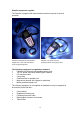
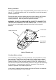
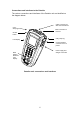
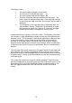
Table Of Contents
- Permalog®
- Patroller
- Scope
- Introduction
- Safety warning
- Battery installation
- Checking Battery voltage
- Connections and interfaces to the Patroller
- Operating the Patroller
- On-Screen Menus
- Specifications
- Fuse information
- Conditions of Use of Permalog® System
- Permalog 1 Deployment Instructions
- Redeployment
- Permalog 2 Deployment Instructions
- Redeployment
- Warranty
- Patents

6
Connections and interfaces to the Patroller
The various connections and interfaces of the Patroller unit are identified on
the diagram below:-
Patroller unit: connections and interfaces
Carry strap lug
Communications
connector to PC or
printer
Power supply and
charger connection
BNC connection to
antenna
On/Off
button
9 Way connector for
GPS communications
Carry
strap lug
LCD display
Back
lighting
button for
LCD
display