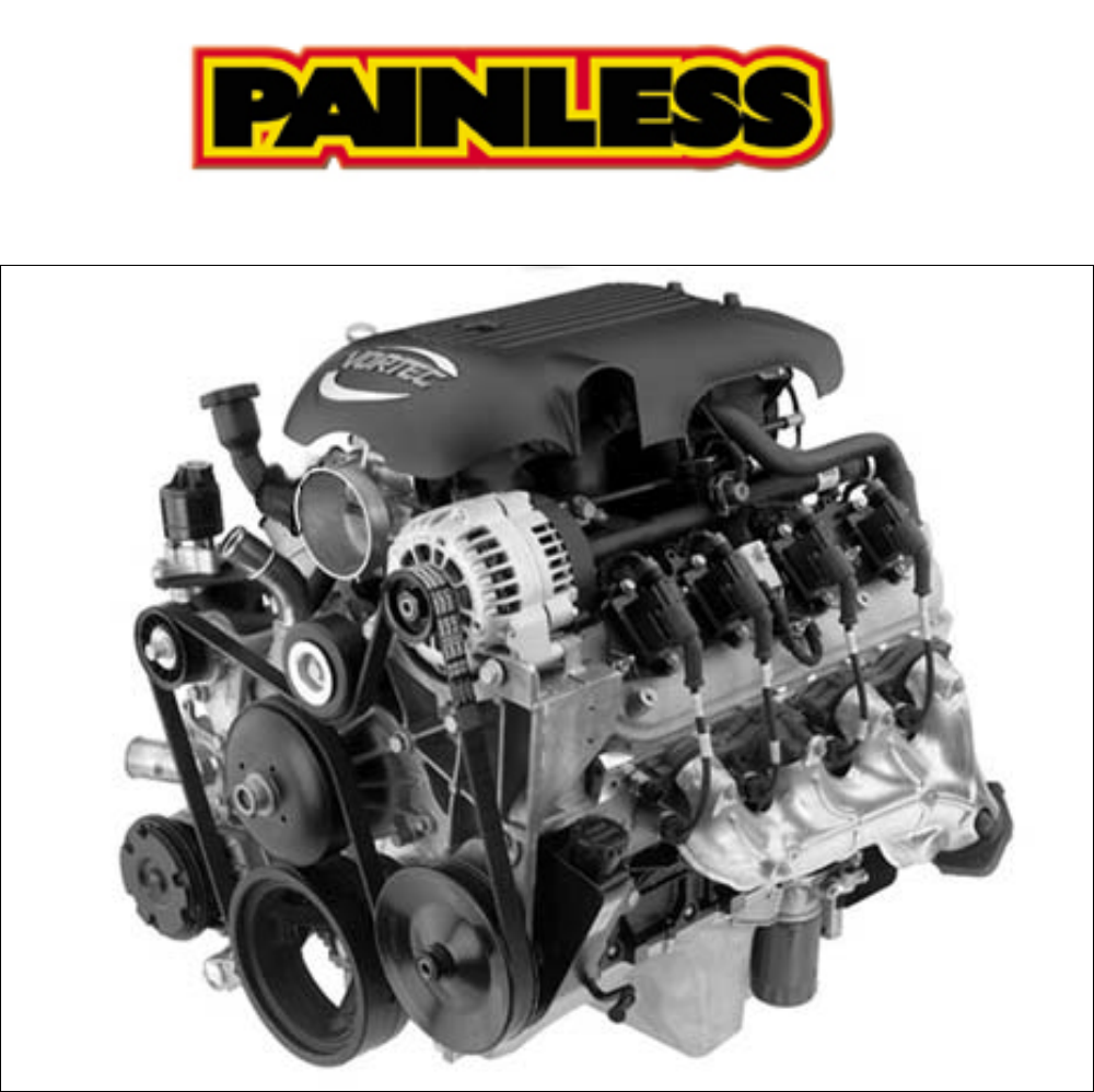
P/N 60219 & 60220 2000 - 2002 GM VORTEC THROTTLE BY WIRE FUEL INJECTION 4.8L, 5.3L & 6.
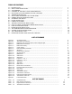
TABLE OF CONTENTS 1.0 2.0 3.0 4.0 5.0 5.1 5.2 6.0 6.1 6.2 6.3 6.4 7.0 7.1 7.2 7.3 8.0 8.1 8.2 INTRODUCTION........................................................................................................................ ABOUT THESE INSTRUCTIONS.................................................................................................. TOOLS NEEDED........................................................................................................................
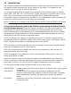
1.0 INTRODUCTION You have purchased what we at Painless Performance Products believe to be the most up-to-date and easiest-to-install automotive fuel injection harness on the market. It is designed for easy installation, even if you have no electrical experience. This harness is designed to be a complete wiring system for the fuel injection system on General Motors 2000 - 2002 4.8L, 5.3L, & 6.
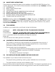
2.0 ABOUT THESE INSTRUCTIONS These instructions provide information for the installation of the 60219 & 60220 TBW Vortec Fuel Injection Harness Kit. The contents of these instructions are divided into major Sections, as follows: 1.0 INTRODUCTION 2.0 ABOUT THESE INSTRUCTIONS 3.0 TOOLS NEEDED 4.0 PRE-INSTALLATION AND HARNESS ROUTING GUIDELINES 5.0 GENERAL INSTALLATION INSTRUCTIONS 6.0 60219 or 60220 VORTEC FUEL INJECTION HARNESS KIT 7.0 GM 00-02 VORTEC SYSTEM WIRE HARNESS INSTALLATION 8.
We do offer some general guidelines and routing practices starting in Paragraph 5.3, general installation instructions in Section 5.0, and precise instruction concerning the electrical connections you will have to make beginning in Section 6.0. To help you begin thinking through the installation of your wire harness, read the following sections: 5.1 TRANSMISSION FUNCTION 5.1.
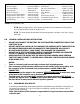
4.8L, 5.3L & 6.0L TBW Vortec Fuel Injection Harness (00 - 02) Part # 60219 & 60220 Main Computer…………………Service#12200411 Fuel Pump Relay………………..Delco# 15-8571 Brake Switch…………………….PPI# 80176 MAF/ IAT Sensor……………….Delco# 213-364 Engine Coolant Temperature……Delco# 213-953 Oxygen Sensor (Pass. Side)……..Delco# AFS106 Oxygen Sensor (Drvr. Side)……..Delco# AFS106 Throttle Body……………………Delco# 17113659 MAP Sensor…………………..…Delco# 213-796 Idle Air Control Motor…………..GM# 17113598 Knock Sensor………………….....
6.1.1 Connect a ground strap or cable (minimum of a 4 Ga. wire) from the negative battery terminal to the chassis (frame). 6.1.2 Connect a ground strap (minimum of a 4 Ga. wire) from the engine to the chassis (frame). Do not rely upon the motor mounts to make this connection. 6.1.3 Connect a ground strap from the engine to the body. 6.2 ROUGH INSTALLATION CAUTION: DISCONNECT THE POWER FROM YOUR VEHICLE BY REMOVING THE NEGATIVE BATTERY CABLE FROM THE BATTERY.
6.4.1 Have all tools and connectors handy. 6.4.2 Select the correct terminal for the wire and application. 6.4.3 Determine the correct wire length and cut the wire. Remember to allow enough slack in the harness and wires at places where movement could occur. DOUBLE CHECK YOUR CALCULATIONS. 6.4.4 Strip insulation away from wire. Only strip as much insulation off as necessary for the type of terminal lug you are using.
7.0 GM 00 – 02 4.8L, 5.3L & 6.0L TBW VORTEC SYSTEM WIRE HARNESS INSTALLATION INSTRUCTIONS 7.1 DASH SECTION INSTALLATION Note: If you have not already done so, read sections 5.0 and 6.0 of these instructions and think through the installation of the harness before securing or cutting any wires. The wires in this group consist of the diagnostic link connector (DLC) (SEE FIGURE 7.
E. FUSE BLOCK IGNITION - This circuit is used to provide power to the injection system. Connect this wire to a terminal/ wire from the ignition switch that is hot in the RUN and CRANK positions. Failure to provide power in the crank position will result in PCM shutdown while the engine is trying to start. Note: You will know this circuit is properly connected if the Check Engine Light is on when the ignition switch is on and while starting. F.
FIGURE 7.3 Brake Switch Relay FIGURE 7.4 Cruise Control FIGURE 7.
WIRE COLOR # OF WIRES IN CONNECTOR Gray, Green/White, Black, Orange 4 Green/White White Pink, Purple Pink Green/ White Gray Gray, Blue, Gray/Black, Brown - LABELED TABLE 7.1 Dash Section Connections 7.2 Fuel Relay VSS Output Tach Brake Switch Fuse Block Ignition AC Request Fuel Test Cruise Control CONNECT TO: Fuel Pump Relay Speedometer Tachometer Brake Switch Ignition Power Compressor B+ See Paragraph 6.2.
F. GROUND (mandatory) - These circuits are used to provide ground for the various devises. Connect these wires under a bolt in the engine block, transmission, or cylinder head. These are the grounds for the entire injection system. For best results from your EFI system, be certain your grounding surfaces are clean and your connections are secure. G.
WIRE COLOR # OF WIRES LABELED IN CONNECTOR Black, Red, Green, Brown, Lt.Blue, Purple, Pink 7 DRVR. COIL Black, Red/ White, Green/ White, Brown/ White, 7 PASS COIL Lt.Blue/ White, Purple/ White, Pink 5 Black, Tan, Black/ White, Pink, Yellow MAF-IAT Lt. Blue/ White 4 Tan/ White, Purple/ White, Black, Pink LEFT O2 SEN 4 Tan, Purple, Black, Pink RIGHT O2 SEN 3 Black/ White, Yellow/ Black, Lt.Green CKP 3 Brown/ White, Pink/ Black, Red CMP 3 Orange/ Black, Lt.
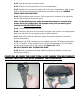
FIGURE 7.8 Oxygen Sensor FIGURE 7.9 MAP Sensor FIGURE 7.10 CMP Sensor FIGURE 7.11 CKP Sensor FIGURE 7.12 Injectors 1, 3, 5, 7 FIGURE 7.
FIGURE 7.14 TPS Sensor FIGURE 7.15 TAC Motor FIGURE 7.16 MAF-IAT Sensor FIGURE 7.17 Driver Side Coil Connector FIGURE 7.18 Passenger Side Coil Connector FIGURE 7.
7.2 TAIL/TRANSMISSION GROUP INSTALLATION Locate the tail section that you earlier separated from the engine group. Begin routing it towards the rear of the vehicle. Be sure to avoid all sharp edges, moving or hot parts, or anything else that may damage the harness. A. BACK-UP- This circuit is used to power the back-up lamps. This wire will connect directly to the back-up light socket. You will need to splice a wire into this circuit in order to accommodate two back-up lights. B.
WIRE COLOR # OF POSITIONS IN CONNECTOR LABELED Blue, Pink/White, Lt.Green, Red, 13 Yellow/Black, Black, Tan/Black, Brown, Lt.Blue/White, Red/Black, Yellow, Pink, White Pink, Black/White, Purple/ White, Yellow, 5 Lt.Green Black/ White, Gray, White, Yellow 4 Red/ Black, Blue/ White Lt.Green/ Black, Purple/ White Gray Purple/ White Lt.
7.4 Converting the 4L60E Transmission Connector to a 4L80E Connector *Note: Harness numbers 60219 and 60220 have been wired for both the 4L60E and the 4L80E. All harnesses have the transmission connector pre terminated to allow use of the 4L60E transmission. In applications where a 4L80E is to be used, follow this procedure to change your transmission connector to ensure all functions of the transmission work properly. See Figure 6.28 for re-pinning the transmission connector 1.
8.0 TROUBLE- SHOOTING INSTRUCTIONS FIGURE 8.1 Fuse Identification 8.1 THE "CHECK ENGINE" LIGHT Normally, the "check engine" light should come on when the ignition is turned on, and then go out a few moments after the engine starts running. If it reappears, or stays on while the engine is running, the computer has detected a problem and a trouble code has been set. NOTE: Most likely the check engine light will come on and stay on when using a computer with the original factory programming.
Before suspecting a computer problem, perform a careful visual inspection. Check under the hood for the same kinds of problems you would look for on a non-computer controlled engine. These include fluid leaks, vacuum leaks, dirty filters, overheating, oil burning, poor connections or loose wires, bad spark plug wires and/or spark plugs, restricted mufflers and exhaust systems, worn mechanical parts, exhaust leaks, and other familiar kinds of problems. Be thorough! You may save a lot of time.
NOTES: 20