
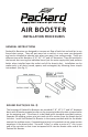
Install Instructions

ELECTRICAL CONNECTION
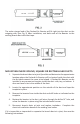
The Packard Air booster should be connected to the appropriate power source
indicated on the nameplate. This product comes equipped for exible cord
connecon which may not be acceptable by local authories. To conform to local
codes, it may be necessary to aach a juncon box at the point where the wires
extend through the duct. Where this air booster is installed as part of a heang duct
system the electrical supply connecon should be suitable for 75° C temperature.
The 6”, 8”, 10”, 12”, and 14” Packard Air Boosters have a juncon box; please check
that it meets the local regulaon upon installaon.
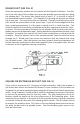
POWER CONTROL OPTIONS
1. Connect directly to the voltage indicated on the nameplate for connuous
operaon.
2. Wire through an “on/o” switch located in a convenient place (Example: A
wall switch in the room to be served).
3. Wire through a thermostat installed in the room to be served. This provides
for automac on/o room temperature control.
4. Wire in parallel to exisng blower. Be sure that the motor is rated to the
same voltage as the air booster. Note that the blower motor controller
cannot be a variable speed tap type, solid state speed control, or any other
type not designed for dual motor control.
5. Wire to voltage indicated on the nameplate through an auxiliary switch,
(pressure or “sail” type) which will automacally energize the air booster
whenever the blower operates.
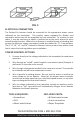
TOOLS REQUIRED:
• Screwdriver
• Drill
• Sheet metal shears
INCLUDED PARTS:
• 8 Sheet metal screws
• 2 wire connectors
• Paper Templates
PACKARDONLINE.COM • 800-334-1769
Must be installed by a licensed contractor.