Packard Bell EasyNote MZ series Disassembly Manual
Table of Contents Overview ..................................................................................................................3 Technician Notes......................................................................................................3 Disassembly Instructions..........................................................................................3 Reassembly Instructions ..........................................................................................3 Required Tools ..
Overview This document contains step-by-step disassembly instructions for the EasyNote MZ series. The instructions are illustrated where necessary with images of the part of the device that is being removed or disassembled. Packard Bell reserves the right to make changes to the EasyNote MZ series without notice. Technician Notes Only technicians authorized by Packard Bell B.V. should attempt to repair this equipment.
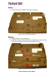
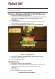
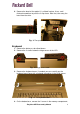
Battery 1. Push the two sliders outwards and pull out the battery. Fig. 1 The bottom of the notebook. Memory 1. Remove battery as described above. 2. Unlock the 2 screws of the memory cover. Note that the screws will not come loose completely; they will stay attached to the cover. Fig. 2 The bottom of the notebook.
3. Lift the door out. Fig. 3 The memory compartment. 4. Push aside the clips securing the memory module. Fig. 4 The memory module 5. Lift the module from the slot.
Note: In case there are 2 modules built in, you will have to remove the top module before removing the bottom module. Wireless LAN Adapter (Mini-PCI or Mini PCI-Express) 1. Remove the battery as described above. 2. Unlock the 2 screws of the add-on card cover. Note that the screws will not come loose completely; they will stay attached to the cover. See Fig. 2. 3. Lift the door out. 4. Disconnect the WLAN antennas from the card. Make a note for each cable whether it is connected to ‘ main’or ‘ aux’ . 5.
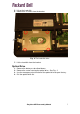
5. Lift out the hard disk. 6. Remove the 4 screws from the bracket. Fig. 6 The hard disk drive. 7. Lift the hard disk from the bracket. Optical Drive 1. 2. 3. 4. Remove the battery as described above. Remove the screw securing the optical drive. See Fig. 2. Use the emergency eject-function of the optical drive to open the tray. Pull the optical drive out.
Fig. 7 The optical drive. 5. Remove the 2 screws to and take away the optical drive bracket. Fig. 8 The optical drive bracket.
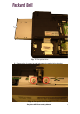
6. Remove the bezel of the optical: it is clicked in place. Use a small flathead screwdriver to push the 2 clips loose. After that, take away the bezel from the drive. Fig. 9 The optical drive bezel. Keyboard 1. Remove the battery as described above. 2. Remove the 2 screws below the hinge covers of the LCD. Fig. 10 Hinge cover screw. 3. Remove the keyboard cover. If needed, you can carefully pry the keyboard cover loose with a flathead screwdriver in the hinge covers. Fig. 11 The keyboard cover. 4.
Fig. 12 The memory compartment. 5. Lift the keyboard. 6. Disconnect the keyboard flatcable. Fig. 13 The bottom of the notebook. 7. Remove the keyboard.
LCD Panel Assembly 1. Remove the battery and keyboard cover as described above (up to step 3). 2. Disconnect the WLAN antenna as described under “WLAN Adapter” (up to step 4). 3. Clear the wireless antenna (it is taped and clipped in place). 4. Disconnect the LCD cable. 5. Remove the 4 screws in the hinges. Fig. 14 The WLAN antenna and hinge screws. 6. Remove the 2 screws in the bottom base. Fig. 15 The bottom of the notebook. 7.
Top Cover and Touchpad 1. Follow all steps above to remove the battery, keyboard, LCD panel, hard disk and optical drive. 2. Remove the 6 screws from the top cover. 3. Disconnect the flatcable of the touchpad. Note: the flatcable only needs to be pulled out, it is not secured. Fig. 16 The touchpad cover. 4. Remove all remaining screws from the bottom base (17x). Fig. 17 The bottom of the notebook. 5. Take away the top cover.
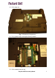
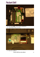
Note: The touchpad is shipped as part of the top cover and does not require further disassembly. Mainboard 1. Follow all steps outlined above. 2. Disconnect the power cable and USB port cable via the memory compartment and wireless LAN adapter compartment. 3. Remove the two screws in the mainboard. Fig. 18 The mainboard. 4. Remove the two hex-bolts adjacent to the VGA port. 5. Lift out the motherboard. 6. Remove the CPU fan and CPU as described below.
Fig. 19 The USB board. 4. Lift out the USB board. Note: To replace the cable to the USB board, the motherboard needs to be removed. CPU and CPU fan 1. 2. 3. 4. Follow all steps to remove the mainboard. Disconnect the power cable of the fan. Remove the 2 screws of the north-bridge heatsink. Remove the 4 screws of the CPU heatsink, in the designated order (1 to 4 engraved in metal clips). Fig. 20 The heatsinks for the CPU and north-bridge.
5. Lift out the CPU fan. 6. To remove the CPU from the socket, turn the screw in the socket 180 degrees to release the CPU. 7. Lift out the CPU. DC Jack 1. Follow all steps to remove the mainboard. 2. Remove the two screws grounding the DC jack cable (one on DC board, one near battery connector). Fig. 21 The DC jack. 3. Lift the DC jack straight up out of the bracket. Speaker Assembly 1. Follow all steps to remove the top cover. 2. Disconnect the speaker cable from the mainboard. 3.
Fig. 23 The LCD panel assembly. 4. Take off the bezel (clicked in place). 5. Disconnect the cables from the inverterboard. 6. Remove the 6 screws of the LCD panel. Fig. 24 LCD panel assembly after top cover removal. 7. Lift out the LCD panel. 8. Remove the 6 screws of the LCD panel brackets, 3 on each side of the panel. 9. Disconnect the LCD cable.
Fig. 25 The LCD cable. Wireless LAN Antenna 1. Follow the steps for the LCD panel up to step 4. 2. Remove the two screws on the top of the LCD panel. Fig. 26 The wireless LAN antenna. 3. Remove the antenna. Note that it is taped in place. Inverter Board 1. Follow the steps for the LCD panel up to step 5. 2. The inverterboard is glued in place. Gently tear it out.
Reassembly Notes When reassembling the device, please take notice of the order in which the parts can be put back and reattached. Notice The information in this guide is subject to change without notice. This guide contains information protected by copyright. No part of this guide may be photocopied or reproduced in any form or by any means without prior written consent from Packard Bell B.V. PACKARD BELL B.V.