Packard Bell EasyNote BG Series Disassembly Guide
Table of Contents Overview ..................................................................................................................3 Technician Notes......................................................................................................3 Disassembly Instructions..........................................................................................3 Reassembly Instructions ..........................................................................................3 Required Tools ..
Overview This document contains step-by-step disassembly instructions for the EasyNote BG series. The instructions are illustrated where necessary with images of the part of the device that is being removed or disassembled. Packard Bell reserves the right to make changes to the EasyNote BG series without notice. Technician Notes Only technicians authorized by Packard Bell B.V. should attempt to repair this equipment.
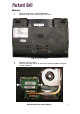
Battery 1. Push aside the 2 latches securing the battery. 2. Fig. 1 Removing the battery. Pull out the battery. Hard Disk 1. 2. Remove the battery as described above. Remove the 3 screws securing the hard disk cover. Fig. 2 The HDD cover.
3. 4. Remove the HDD cover. Pull the plastic tab on the drive to disconnect it. Fig. 3 The HDD cover. 5. 6. Take the drive out if its compartment. Remove the 4 screws of the HDD bracket. Fig. 4 The HDD flat cable. 7. Take away the bracket from the hard drive.
Wireless LAN 1. 2. Remove the battery as described above. Remove the 3 screws securing the hard disk cover. 3. 4. 5. Fig. 5 The HDD cover. Remove the HDD cover. Disconnect the 2 antenna cables from the Wireless LAN card. Remove the 2 screws holding the card.
Fig. 6 The wireless LAN screws and cables. 6. The left end of the card will now jump up. Fig. 7 The wireless LAN card. 7. Carefully take out the Wireless LAN card.
Memory 1. 2. Remove the battery as described above. Remove the 5 screw securing the CPU cover. Fig. 8 The CPU cover. 3. 4. Remove the CPU cover. Release the metal clips that secure the memory modules and take out the module(s). Fig. 9 The bottom of the notebook.
Keyboard 1. 2. Remove the battery as described above. There are 5 small slots; insert a small flat-blade screwdriver in each slot to unlatch the keyboard. Fig. 10 The keyboard clips. 3. 4. Carefully unlock the white clamp. Slide the keyboard cable out of the connector. Fig. 11 The keyboard flatcable.
CPU Fan 1. Remove the battery and CPU cover as described above. 2. 3. 4. Fig. 12 The CPU fan. Remove the single screw holding the CPU fan. Disconnect the fan’ s power cable. Take the fan out of the notebook. Heatsink 1. 2. 3. 4. Remove the battery and CPU fan as described above. Remove the 6 screws holding the heatsink. Carefully lift the copper arm a little. Be careful with the thermal paste between the heatsink and the mainboard. Slide the heatsink to the left out of the casing.
Fig. 13 The heatsink. CPU 1. 2. Remove the battery, fan and heatsink as described above. Use a small flatbed screwdriver to unlock the CPU. Fig. 14 The CPU. Top Cover and Touchpad 1. 2. 3. Remove the battery and keyboard as described above. Remove the single screw of the CPU fan, but do not remove the CPU fan itself. Remove the 12 screws holding the top cover.
Fig. 15 The top cover screws. 4. 5. 6. Turn over the unit and remove the 3 screws securing the top cover. Disconnect the 2 cables. Unclip the latches around the edge of the top cover. Fig. 16 The top cover screws. LCD Assembly 1. Remove the battery, hard disk, keyboard, CPU fan and top cover as described above.
2. 3. 4. Disconnect the 6 cables connecting the LCD panel to the mainboard. Disconnect the cables from the WLAN card. Make sure the tape securing them is removed everywhere. Remove the 6 hinge screws. Fig. 17 The hinge screws and LCD cable. 5. Remove the 5 rubber plugs and the 5 screws underneath them.
Fig. 18 The LCD cover screws. 6. 7. Lift of the bezel. The LCD panel and webcam will be revealed. Remove the 4 screws. Fig. 19 The LCD panel screws. 8. Take out the LCD panel.
VGA Board 1. 2. 3. Remove the battery, keyboard, CPU fan and top cover as described above. Disconnect the VGA board connector cable from the mainboard. Remove the 2 screws. Fig. 20 The connectors and screw for VGA board. 4. Remove the VGA board. Fig. 21 The VGA board.
Power/Ethernet Board 1. 2. 3. Remove the battery, keyboard, CPU fan and top cover as described above. Disconnect the cable connector. Remove the 2 screws holding the board. Fig. 22 The power/Ethernet board. 4. Remove the board. Mainboard 5. 6. 7. Remove the battery, keyboard, CPU fan and top cover as described above. Disconnect the 7 cables from the mainboard. Remove the 3 screws.
Fig. 23 The mainboard screws and connectors. 8. Remove the mainboard.
Reassembly Notes When reassembling the device, please take notice of the order in which the parts can be put back and reattached. Notice The information in this guide is subject to change without notice. This guide contains information protected by copyright. No part of this guide may be photocopied or reproduced in any form or by any means without prior written consent from Packard Bell B.V. PACKARD BELL B.V.