AeGIS NPB9000 Series QUICK REFERENCE GUIDE PACH & COMPANY www.pach-co.
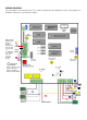
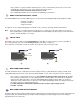
WIRING DIAGRAM A proper installation of the AeGIS system is very essential. You MUST follow the installation procedures, block diagrams and installation requirements as specified in this chapter. Optional 26 Bit Wiegand Card 9 Reader or Wiegand RED Radio Reader BLACK Input. We will not resposible WHITE for incompatibility GREEN issue if using other than Pach & Co 10 Proximity Reader.
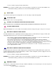
13 2 1 14 11 EXPANSION RELAY PANEL MX79012 - MX79120 12 1 MAIN RELAY CONTROL PANEL MS79012 - MS79120
14 15 15 RJ71X12 1 RJ71X24 GROUNDING Grounding the AeGIS 9000NC, MS79xxx and MX79xxx steel enclosure are essential. Please comply with all local ordinances and industry standard procedures to ensure a complete and safe ground. Recommended earth grounds are: • • • • • Use 18-gauge solid wire for grounding. Installing a ground steel rod from the steel enclosure to the earth ground, use the same grounding point for best ground.
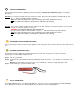
• Two Conductors, 18-gauge shielded stranded must be used for communication. Ground only one end of the shielded to the earth ground. Use the same earth ground for best ground. See installation instruction if ASP1 Surge Protector is used. • Up to eight AeGIS 9000NC can be connected to the Main Relay Control Panel. 3 DOOR STRIKE OR ELECTRICAL STRIKE The AeGIS NPB9000 Series provides TWO relay form "C" dry contact: Normally Open (NO) and Normally Closed (NC).
• Use two conductors 8-gauge shielded stranded wires. WARNING: The connection is polarity sensitive. Connect the battery (+) terminal to the connector labeled (BAT) on the AeGIS and the battery (-) terminal to the connector labeled LCOM on the AeGIS. 7 NIGHT LIGHT 14V 0.080A 15,000 Average life hours light bulbs. Use the same rating of replacement light bulb. 8 TELEPHONE LINE Optional telephone line for remote programming.
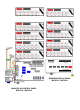
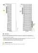
14 TENANTS PHONE WIRING The RJ71X12 and RJ71X24 are supplied by Pach and Company. The label UP or TOP must at top. Use 22-gauge twisted wire. RJ71X12 has 2-columns (A and B) and each column has 50 pins. Each pin is labeled (TNT-T1, TNT-R2, CO-T1, COT2,......., TNT-T12, TNT-R12, CO-T12, CO-R12). TNT is the output telephone wires (Tip and Ring) to the tenant apartment or house. CO is the input from telephone company wires (dial tone, tip and ring).
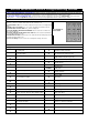
AeGIS NPB9000 Series Programming Guide LOCAL PROGRAMMING 1) PRESS 0 AND # SIMULTANEOUSLY THEN RELEASE, the display screen stops scrolling (If the display screen is still scrolling repeat this step again) then enter the valid 4-digit Master Code (default Master Code: 0000). Now, you are in programming mode and see table below to continue.