
User's Manual
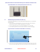

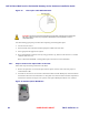
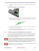
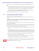
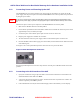


Table Of Contents
- Chapter 1 Introduction
- Chapter 2 Overview
- 2.1 Overview of ONT-2-E4xxxi Multi-service Residential Gateway Series
- 2.2 EPON Multi-service Gateway Series Hardware Interface
- 2.3 Supported Residential Gateway (RG) Features
- 2.3.1 Network Address Translation (NAT)/NAPT (Network Address Port Translations)
- 2.3.2 Dynamic Domain Name System (DDNS)
- 2.3.3 Dynamic Host Configuration Protocol (DHCP) Client and Server
- 2.3.4 Security Firewall and Rich Packet Filtering
- 2.3.5 Advanced Quality of Service,
- 2.3.6 Virtual Server
- 2.3.7 Flexible Management Interfaces including Web GUI
- 2.4 Additional Features
- 2.5 Product Specifications
- 2.6 Physical Characteristics
- Chapter 3 Hardware Description
- 3.1 Package Contents
- 3.2 Accessories
- 3.3 ONT-2-E4xxxi Multi-service Residential Gateway Series Enclosure
- 3.4 LED Diagnostics on Front Panel
- 3.5 Rear Panel and Interface Description
- 3.6 Ethernet Connections
- 3.7 EPON SC/APC Fiber Optic Network Interface
- 3.8 Voice Telephony Interfaces (Standard Telephone)
- 3.9 RF Overlay
- 3.10 Power
- Chapter 4 Installing the ONT-2-E4xxxi Multi-service Residential Gateway Series
- 4.1 Cautions and Warnings
- 4.2 Pre-Installation Check
- 4.3 Tools and Materials Needed
- 4.4 System Requirements
- 4.5 Situating the EPON Multi-service Gateway ONT
- 4.6 Wall-Mounting the ONT Using the Fiber Tray
- 4.7 Wall-Mounting the ONT without the Fiber Tray
- 4.8 Vertical or Tower Mounting the ONT
- 4.9 Connecting the EPON Optical Fiber to the ONT
- 4.10 Connecting Telephones to the EPON Multi-service Gateway ONT
- 4.11 Connecting Premises LAN Ethernet Wiring
- 4.12 Connecting Power and Powering Up the ONT
- 4.13 Connecting to the GUI Interface of the ONT
- Index

ONT-2-E4xxxi Multi-service Residential Gateway Series Hardware Installation Guide
TM 87-10879 Rev. A UNRELEASED DRAFT 31
4.12 Connecting Power and Powering Up the ONT
The EPON Multi-service Gateway ONT has a DC power input for connecting to an external 12 volt DC
power supply. Once the power input is connected, the EPON Multi-service Gateway ONT can be powered on
by using the power switch.
Only use the 12 Volt DC power supply and integrated cord that was shipped with the EPON Gateway ONT.
The plug for the power supply is specific to the geographic region in which the EPON Gateway ONT is distrib-
uted.
Follow these steps to connect power and power on the EPON Multi-service Gateway ONT.
1. Make sure the ON/OFF switch is in the OFF position.
2. Ensure that the operational location of the ONT is within reach of a suitable AC outlet. The power cord is
approximately 5 feet (1.52 meters) in length.
3. Connect the power cord to the DC power input connector on the rear of the unit.
4. Plug the power supply into a suitable AC wall outlet.
5. Tie down and strain-relieve the power supply cable to avoid accidental power loss to the unit.
6. Press the ON/OFF switch to ON to apply power to the ONT, and check that the Power LED on the front
of the ONT is green.
See Figure 17 for a closeup of the Backup Power connector in the rear panel of the ONT.
Figure 17 Rear Backup Power Connector
Powering by the Backup Power connector is only effective when the power ON/OFF switch is at the OFF
position.
4.13 Connecting to the GUI Interface of the ONT
1. Open your web browser and type http://192.168.1.1 in the browser's address box. This number is the
default IP address for this ONT. Press Enter.
2. A username and password window will appear. The default username and password are “admin” and
“admin” respectively. Press OK to proceed.
3. If the authentication succeeds, the ONT’s GUI homepage “Device Info Summary” screen displays.
Note