
User's Manual

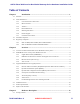
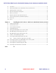


Table Of Contents
- Chapter 1 Introduction
- Chapter 2 Overview
- 2.1 Overview of ONT-2-E4xxxi Multi-service Residential Gateway Series
- 2.2 EPON Multi-service Gateway Series Hardware Interface
- 2.3 Supported Residential Gateway (RG) Features
- 2.3.1 Network Address Translation (NAT)/NAPT (Network Address Port Translations)
- 2.3.2 Dynamic Domain Name System (DDNS)
- 2.3.3 Dynamic Host Configuration Protocol (DHCP) Client and Server
- 2.3.4 Security Firewall and Rich Packet Filtering
- 2.3.5 Advanced Quality of Service,
- 2.3.6 Virtual Server
- 2.3.7 Flexible Management Interfaces including Web GUI
- 2.4 Additional Features
- 2.5 Product Specifications
- 2.6 Physical Characteristics
- Chapter 3 Hardware Description
- 3.1 Package Contents
- 3.2 Accessories
- 3.3 ONT-2-E4xxxi Multi-service Residential Gateway Series Enclosure
- 3.4 LED Diagnostics on Front Panel
- 3.5 Rear Panel and Interface Description
- 3.6 Ethernet Connections
- 3.7 EPON SC/APC Fiber Optic Network Interface
- 3.8 Voice Telephony Interfaces (Standard Telephone)
- 3.9 RF Overlay
- 3.10 Power
- Chapter 4 Installing the ONT-2-E4xxxi Multi-service Residential Gateway Series
- 4.1 Cautions and Warnings
- 4.2 Pre-Installation Check
- 4.3 Tools and Materials Needed
- 4.4 System Requirements
- 4.5 Situating the EPON Multi-service Gateway ONT
- 4.6 Wall-Mounting the ONT Using the Fiber Tray
- 4.7 Wall-Mounting the ONT without the Fiber Tray
- 4.8 Vertical or Tower Mounting the ONT
- 4.9 Connecting the EPON Optical Fiber to the ONT
- 4.10 Connecting Telephones to the EPON Multi-service Gateway ONT
- 4.11 Connecting Premises LAN Ethernet Wiring
- 4.12 Connecting Power and Powering Up the ONT
- 4.13 Connecting to the GUI Interface of the ONT
- Index
ONT-2-E4xxxi Multi-service Residential Gateway Series Hardware Installation Guide
TM 87-10879 Rev. A UNRELEASED DRAFT v
List of Figures
Figure 1 LED Indicators on EPON Multi-service Gateway ONT ................................................. 15
Figure 2 Rear Panel Ports on the ONT-2-E4020iWn..................................................................... 17
Figure 3 SC/APC Optical Fiber Plugged into Optical Network Interface ..................................... 18
Figure 4 Rear Backup Power Connector ........................................................................................ 19
Figure 5 Side Backup Power Connector ........................................................................................ 19
Figure 6 Schematic of the Back of the Fiber Tray ......................................................................... 24
Figure 7 Fiber Tray with Cover Installed on Wall ......................................................................... 24
Figure 8 EPON Multi-service Gateway Wall-mounted onto Fiber Tray ....................................... 25
Figure 9 Schematic of the Bottom of EPON Multi-service Gateway ............................................ 25
Figure 10 EPON Multi-service Gateway Wall-mounted ............................................................... 26
Figure 11 EPON Multi-service Residential Gateway ONT Vertically-Mounted .......................... 26
Figure 12 Snapping the ONT onto the Fiber Tray ......................................................................... 27
Figure 13 Typical Wall Plate Example .......................................................................................... 27
Figure 14 Fiber Optic Cable Minimum Bend ................................................................................ 28
Figure 15 SC/APC Optical EPON Port .......................................................................................... 28
Figure 16 SC/APC EPON Connector Compartment ..................................................................... 29
Figure 17 Rear Backup Power Connector ...................................................................................... 31
Figure 18 Device Info Summary Screen ........................................................................................ 32