
User's Manual
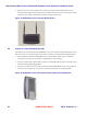


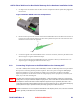


Table Of Contents
- Chapter 1 Introduction
- Chapter 2 Overview
- 2.1 Overview of ONT-2-E4xxxi Multi-service Residential Gateway Series
- 2.2 EPON Multi-service Gateway Series Hardware Interface
- 2.3 Supported Residential Gateway (RG) Features
- 2.3.1 Network Address Translation (NAT)/NAPT (Network Address Port Translations)
- 2.3.2 Dynamic Domain Name System (DDNS)
- 2.3.3 Dynamic Host Configuration Protocol (DHCP) Client and Server
- 2.3.4 Security Firewall and Rich Packet Filtering
- 2.3.5 Advanced Quality of Service,
- 2.3.6 Virtual Server
- 2.3.7 Flexible Management Interfaces including Web GUI
- 2.4 Additional Features
- 2.5 Product Specifications
- 2.6 Physical Characteristics
- Chapter 3 Hardware Description
- 3.1 Package Contents
- 3.2 Accessories
- 3.3 ONT-2-E4xxxi Multi-service Residential Gateway Series Enclosure
- 3.4 LED Diagnostics on Front Panel
- 3.5 Rear Panel and Interface Description
- 3.6 Ethernet Connections
- 3.7 EPON SC/APC Fiber Optic Network Interface
- 3.8 Voice Telephony Interfaces (Standard Telephone)
- 3.9 RF Overlay
- 3.10 Power
- Chapter 4 Installing the ONT-2-E4xxxi Multi-service Residential Gateway Series
- 4.1 Cautions and Warnings
- 4.2 Pre-Installation Check
- 4.3 Tools and Materials Needed
- 4.4 System Requirements
- 4.5 Situating the EPON Multi-service Gateway ONT
- 4.6 Wall-Mounting the ONT Using the Fiber Tray
- 4.7 Wall-Mounting the ONT without the Fiber Tray
- 4.8 Vertical or Tower Mounting the ONT
- 4.9 Connecting the EPON Optical Fiber to the ONT
- 4.10 Connecting Telephones to the EPON Multi-service Gateway ONT
- 4.11 Connecting Premises LAN Ethernet Wiring
- 4.12 Connecting Power and Powering Up the ONT
- 4.13 Connecting to the GUI Interface of the ONT
- Index

ONT-2-E4xxxi Multi-service Residential Gateway Series Hardware Installation Guide
30 UNRELEASED DRAFT TM 87-10879 Rev. A
Follow these steps to connect the telephones or telephony equipment to the EPON Multi-service Gateway
ONT:
1. Telephony equipment is generally supplied with a cable that includes an RJ-11 type plastic connector on
the opposite or both ends. Insert the RJ-11 connector for the first telephone (or other equipment) into the
#1 telephone port (Phone1) located on the rear panel of the EPON Multi-service Gateway ONT.
2. If a second telephony device is to be connected, plug its RJ-11 connector into the #2 telephone port
(Phone2) located on the rear panel of the EPON Multi-service Gateway ONT.
Refer to Figure 2 Rear Panel Ports for the location of the telephone port connectors.
4.11 Connecting Premises LAN Ethernet Wiring
The ONT-E-4020i provides four Ethernet network interfaces.
Each Ethernet Port (LAN1 - LAN4) can be individually mapped to a VLAN as necessary for service de-
ployment.
All Ethernet interfaces auto-detect whether the connectivity cable is straight-through or cross-over and con-
figure themselves accordingly. In addition, all Ethernet interfaces auto-negotiate by default to operate at the
speed and duplex mode of attached devices.
The Ethernet link length can be no greater than 100 m (≈ 328 ft) as defined by the IEEE 802.3 Ethernet
Standard for 10/100/1000BASE-T.
The following steps are an example of how you can directly connect a network interface card, Ethernet set top
box (STB), or an Ethernet switch, hub, or router on the customer premises Local Area Network (LAN). The
service provider or cable operator may provide any site-specific instructions.
1. Use port 1 to connect the household’s primary computer (or switch/router that supports the primary data
services).
2. Ethernet compatible CPEs (computers, switches, routers, etc) utilize standard Ethernet wiring, which
includes an RJ-45 connector on each end of the wire. Plug one end of the Ethernet cable into the target
CPE, and plug the other end of the wire into the Gigabit Ethernet Port #1 on the rear panel of the EPON
Multi-service Gateway ONT. Refer to Figure 2 Rear Panel Ports for the location of the Ethernet ports.
3. Use ports 2, 3, and 4 to connect any remaining Ethernet equipment, such as additional computers,
Ethernet Set Top Boxes, or game controllers with Ethernet ports.
4. To organize the connected cables and reduce stress on the physical connections, it is recommended to
tie-off and strain relieve the cable bundle connected to the rear on the ONT.
5. It is also advisable to label the individual cables noting the CPE and location to which it is connected.
The actual equipment that is connected to ports 1, 2, 3, and 4 may depend on how the Service Provider has
provisioned each port, such as for data or IPTV services.
Note