
User's Manual
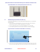
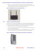
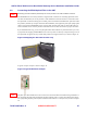
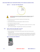
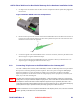
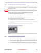


Table Of Contents
- Chapter 1 Introduction
- Chapter 2 Overview
- 2.1 Overview of ONT-2-E4xxxi Multi-service Residential Gateway Series
- 2.2 EPON Multi-service Gateway Series Hardware Interface
- 2.3 Supported Residential Gateway (RG) Features
- 2.3.1 Network Address Translation (NAT)/NAPT (Network Address Port Translations)
- 2.3.2 Dynamic Domain Name System (DDNS)
- 2.3.3 Dynamic Host Configuration Protocol (DHCP) Client and Server
- 2.3.4 Security Firewall and Rich Packet Filtering
- 2.3.5 Advanced Quality of Service,
- 2.3.6 Virtual Server
- 2.3.7 Flexible Management Interfaces including Web GUI
- 2.4 Additional Features
- 2.5 Product Specifications
- 2.6 Physical Characteristics
- Chapter 3 Hardware Description
- 3.1 Package Contents
- 3.2 Accessories
- 3.3 ONT-2-E4xxxi Multi-service Residential Gateway Series Enclosure
- 3.4 LED Diagnostics on Front Panel
- 3.5 Rear Panel and Interface Description
- 3.6 Ethernet Connections
- 3.7 EPON SC/APC Fiber Optic Network Interface
- 3.8 Voice Telephony Interfaces (Standard Telephone)
- 3.9 RF Overlay
- 3.10 Power
- Chapter 4 Installing the ONT-2-E4xxxi Multi-service Residential Gateway Series
- 4.1 Cautions and Warnings
- 4.2 Pre-Installation Check
- 4.3 Tools and Materials Needed
- 4.4 System Requirements
- 4.5 Situating the EPON Multi-service Gateway ONT
- 4.6 Wall-Mounting the ONT Using the Fiber Tray
- 4.7 Wall-Mounting the ONT without the Fiber Tray
- 4.8 Vertical or Tower Mounting the ONT
- 4.9 Connecting the EPON Optical Fiber to the ONT
- 4.10 Connecting Telephones to the EPON Multi-service Gateway ONT
- 4.11 Connecting Premises LAN Ethernet Wiring
- 4.12 Connecting Power and Powering Up the ONT
- 4.13 Connecting to the GUI Interface of the ONT
- Index

ONT-2-E4xxxi Multi-service Residential Gateway Series Hardware Installation Guide
28 UNRELEASED DRAFT TM 87-10879 Rev. A
Figure 14 Fiber Optic Cable Minimum Bend
CAUTION: Ensure that you inspect and clean every fiber optic connector prior to mating the
fiber ends. Failure to do so may compromise performance of the equipment, or cause
component failure.
Take the following appropriate precautions when inspecting and cleaning fiber optics:
1. Turn off all laser sources
2. Ensure that the cable is disconnected from equipment at both ends of the cable
3. Wear appropriate safety glasses if required
4. Keep unplugged fiber connectors clean by using a protective cap, which is to be stored in a re-sealable
container when not in use.
Refer to document TN-08-001 “Cleaning Fiber Optic Connectors” for more information.
4.9.1 Steps to Connect the Optical Fiber to the ONT
Follow these steps for making connections to the ONT:
1. Remove the protective covers from the tips of the SC optical connector at the end of the jumper or
terminated fiber cable.
2. Insert the SC connector on one end of the cable into the ONT’s SC/APC EPON port, which is located on
the left side of the unit as viewed from the rear. The plastic cover of the SC/APC connector compartment
must first be removed. See Figure 15 for a picture of the optical EPON port with the cover removed.
Figure 15 SC/APC Optical EPON Port